WEB Configuration
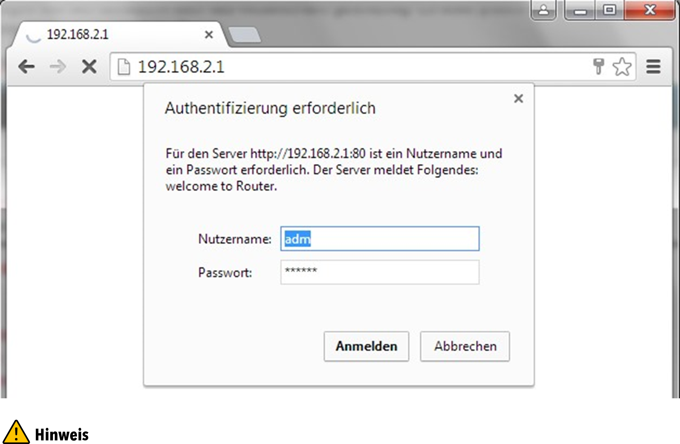
The TK800 series routers have a built-in web server for configuration. Open http://192.168.2.1 in the browser. Enter the user name (default: adm) and password (default: 123456) and confirm with Login.
For security reasons, the password should be changed after the first login. Choose a password with at least 10 digits, upper and lower case letters, special characters and numbers.

The router allows parallel access of up to four users via the web interface. However, it should be avoided to configure the router simultaneously.
After the successful login, the web interface of the router appears.
The web interface of the TK800 is divided into 4 areas. On the left side is the Main navigation with the items Administration, Network, etc. In the upper area is the Detail navigation. In this example with Status (active) and Basic Setup. In the middle of the web interface the current status and configuration options are shown. On the right side active alarms are displayed.
Administration
On the left side you will find the menu item “Administration”. Touching it with the mouse opens a submenu. In the administration area is the status overview and the configuration for the administration of the router.
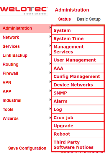

With Restricted user rights (not administrator) some items are missing in the menu. Restricted users cannot configure the router, the Apply & Save option is missing.
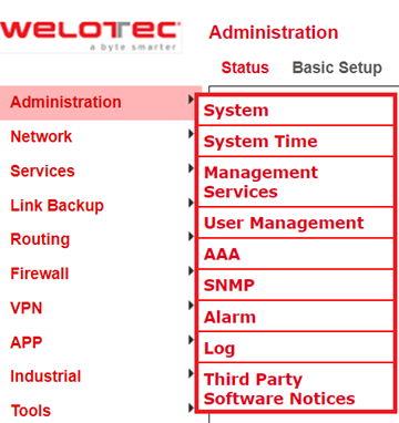
System
Status
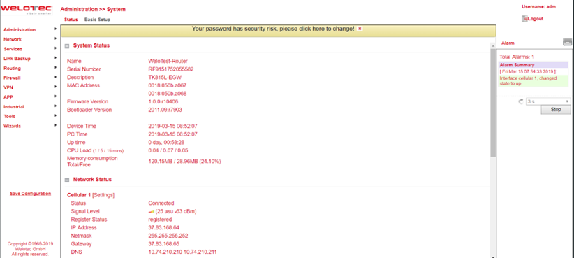
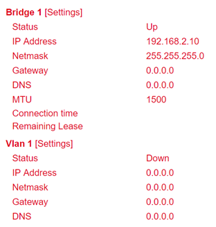
Under Administration > System > Status you will find the most important Status information of the router at a glance. Via the button Sync Time the time of the router can be synchronized with the time of the connected PC. If you use the default password for login (123456), a yellow bar will indicate that this is a security risk and should be changed. You can do this by clicking on the hint. We strongly recommend that you do this for security reasons!
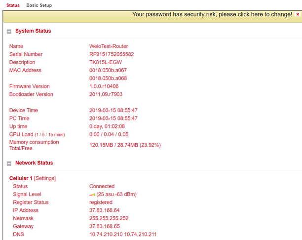
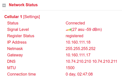
The Network Status is located under the System Status. By clicking on the gray [+] the information about the individual network interfaces appears. Here you will find all important information about the status of the individual interfaces.
By clicking on [Settings] next to the individual interfaces (e.g. Cellular 1) you will be taken directly to the configuration of the interfaces.
Basic Setup
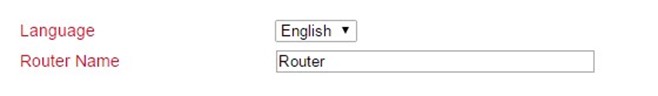
Under Administration > System > Basic Setup you can change the language of the router and the router name. Currently only English is supported as language. The router name can be used as unique name of the router. Here a meaningful name should be chosen.
System Time
To ensure coordination between the TK800 router and other devices, the system time should be the same on all devices and the time zone should be set correctly. Under Administration > System Time you will find all the settings for the system time of the TK800 Router. The time can be set manually or automatically updated by a time server via the Simple Network Time Protocol (SNTP). In addition, it is possible to automatically supply devices connected to the router with the current time information via the NTP server.
System Time Configuration
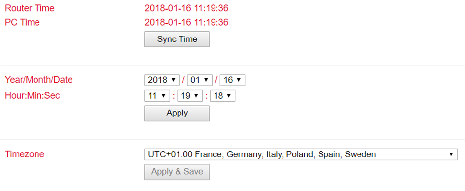
Under Administration > System Time you will find an overview and local settings for the system time of the router. Via Sync Time you can synchronize the time of the router with the time of the PC.
Among the settings there is also the possibility to set the router time and date manually.
Under Timezone the current time zone can be selected.
The default is UTC+1 (time zone in Germany, Austria and Switzerland).
SNTP Client
SNTP (Simple Network Time Protocol) is a protocol for time synchronization of the clocks of network devices. SNTP provides extensive mechanisms to synchronize the time over a subnet, network, or the Internet. Typically, SNTP can achieve accuracies of 1 to 50 ms, depending on the characteristics of the synchronization source and routers. The goal of SNTP is to synchronize all devices in a network with a clock in order to run distributed applications based on one time source.
Under Administration > System Time > SNTP Client the settings for the current time can be made. The router can then update the time via a public or private time server.
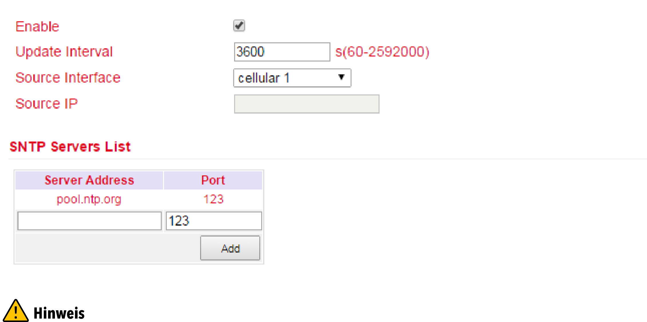
Before setting up an SNTP server, make sure that the SNTP server is reachable. Especially in the case of a domain name, it should be checked whether the DNS server is configured correctly for name resolution.
Either a source interface or a source IP can be configured.
After the successful update of the time, the following appears in the log under Administration > Log.

NTP Server
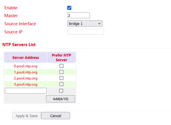
The settings for the time server are located under Administration > System Time > NTP Server. In this case, the TK800 can work as a time server for the connected devices.
Via Master the stratum can be specified. This indicates how precise the server is. Values between 2 and 15 can be specified. The lower, the closer the router is to an atomic or radio clock (from a topological point of view).
The Source Interface specifies the interface at which the devices can request the NTP service of the router. Alternatively, a Source IP can be determined via which the NTP service is provided.
It is important that NTP server and NTP client work independently of each other, this also means that for both NTP client and NTP server an NTP service from the Internet must be entered. For this purpose the address of the NTP service is entered under Server Address. It is possible to enter more than one service.
Management Services
Under Administration > Management Services the access to the web interface with HTTP and HTTPS as well as to the Command Line Interface (CLI) via Telnet and SSH can be configured.
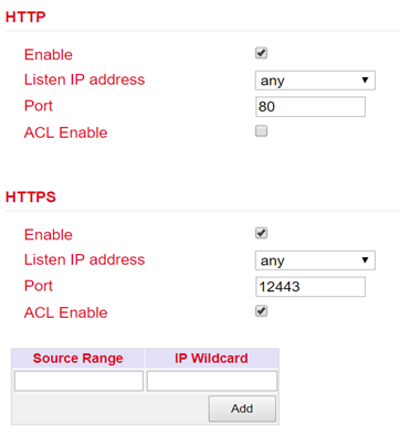
HTTP
HTTP is the abbreviation for Hypertext Transfer Protocol and is used to access the router’s web interface.
HTTPS
HTTPS is the abbreviation for Hypertext Transfer Protocol Secure and uses SSL (Security Socket Layer) for encrypted transmission of HTTP.
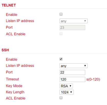
TELNET
TELNET is used to access the Command Line Interface (CLI) of the router.
SSH
SSH is the abbreviation for Secure Shell and is an encrypted service comparable to Telnet.
Configuration
For each service it is possible to select whether it should be activated or deactivated and on which IP address this service may be addressed.
To do this, simply check or uncheck Enable. Under Port the TCP port for the respective service can be selected. With ACL Enable an access restriction can be set up for each port. If ACL Enable is activated, you can enter in the Source Range and IP Wildcard fields which IP address or IP address ranges are allowed to access the router via this port. For SSH, you can also define the Timeout for an SSH session to the router.
If there is no activity during the timeout period, the connection is terminated. Under Key Mode and Key Length the encryption standard and the key length can be selected.
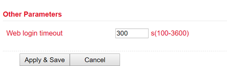
Via Other Parameters you can set the Web login timeout. This specifies how long a web interface session remains if no input is made.
If the timeout time has expired without any input, then the logged in user will be logged out automatically.
User Management
Under Administration > User Management the users that have access to the router can be configured. The router distinguishes between the administrator and the standard user. The administrator is created by the system (adm). The administrator can create other standard users with limited rights.
The Administrator user is suitable for configuring and managing the router. The Standard user is suitable for monitoring and checking the router.
Create a User
Under Administration > User Management > Create a User you can create additional users.
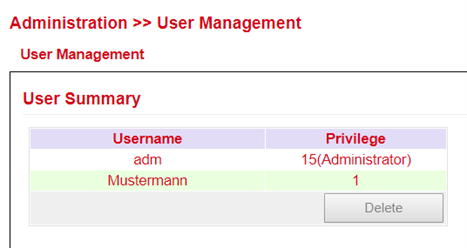
A Username and Password must be created and the Permission (Privilege) must be entered. Privilege 1 to 14 is for standard users (read only) and privilege 15 for administrators (full access). Under User Summary you will find a list of all users and their privileges.
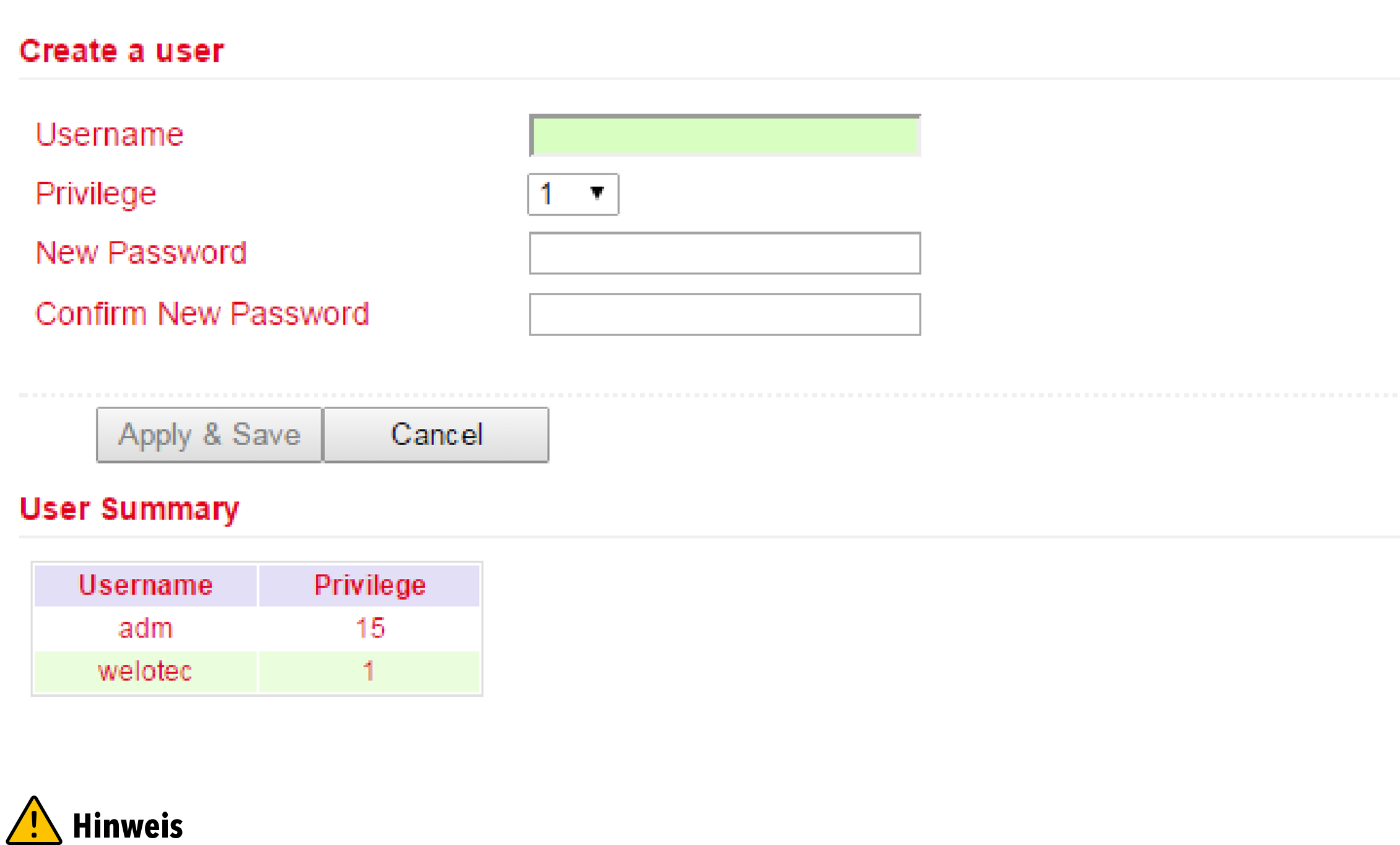
A secure password should consist of at least 8 characters and preferably contain upper/lower case, numbers and special characters. The username root is reserved for the operating system of the router.
Modify a User
If you want to make adjustments to users, then you can edit them under Administration > User Management > Modify a User. Permissions and passwords can be changed.
Under User Summary a user can be selected and then edited under Modify a user.
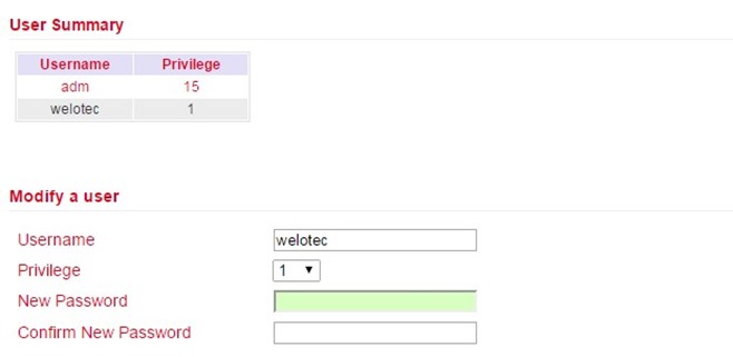
When selecting the adm user, the user name can be changed, e.g. to admin, as of firmware version V1.0.0.r10406. Please always remember to change the default password (123456) of the adm user to a secure password.
Remove Users
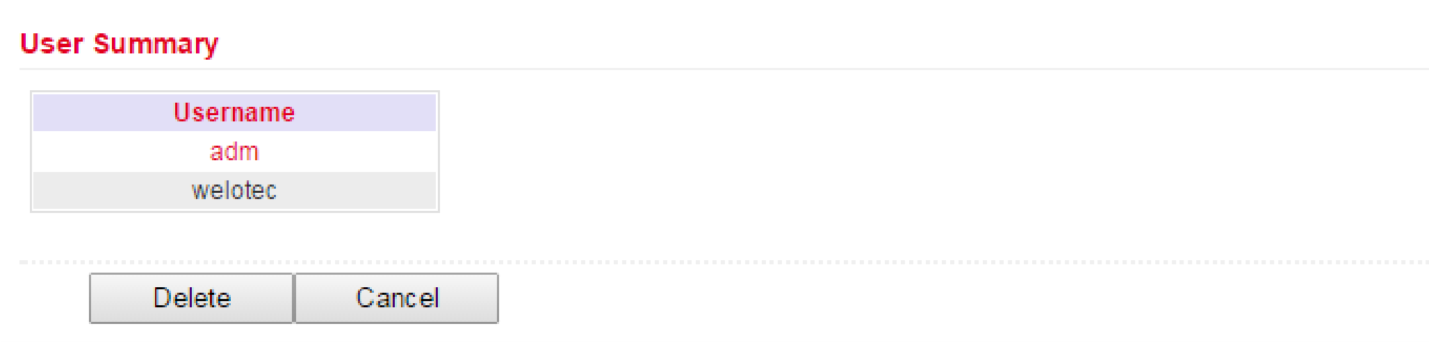
Under Administration > User Management > Remove Users you can delete users from the TK800. Select the user to be deleted under User Summary and delete it via the Delete button.
AAA
AAA or Triple-A stands for Authentication, Authorization and Accounting. Here, authentication takes over access control, whether a user is allowed to use the device or the network. Authorization checks which services the user is allowed to use on the network. Accounting ensures that all accesses and events and the use of resources in the network are logged correctly.
With AAA, not all security services have to be used. It is also possible that only one or two services are used in a network. A AAA infrastructure is usually set up as a client-server architecture. The TK800 acts here as AAA client. Radius, Tacacs+ and LDAP are supported for this purpose.
Radius
Radius stands for Remote Authentication Dial-In User Service and is a client-server protocol used for authentication, authorization and accounting.
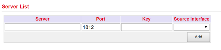
You can enter the FQDN or IP address of the server, the port, the key for the Radius server and the source interface here.
Tacacs+
Tacacs+ stands for Terminal Access Controller Access Control System and is a client-server protocol used for authentication, authorization and accounting.
It is used for client-server communication between AAA servers and a Network Access Server (NAS).
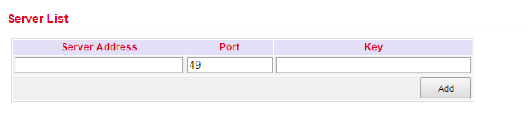
You can enter the corresponding data here at Server Address, Port and Key.
LDAP
LDAP stands for Lightweight Directory Access Protocol and is suitable for querying and modifying information from directory services. LDAP is based on the client-server model.
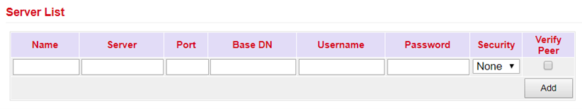
Enter the data for your LDAP server here.
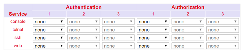
AAA Settings
Config Management
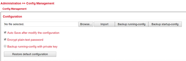
Under Administration > Config Management the current configuration can be saved, an existing configuration can be uploaded or the router can be reset to the default configuration.
Importing an existing configuration
To import an existing configuration, an existing configuration file must be selected via Browse…. After the correct file has been selected, the configuration can be imported to the router via Import. After successfully importing the configuration, the router displays a button for restarting. After the restart the router will have the new configuration.
Saving an existing configuration
Via Backup running-config the current configuration incl. the unconfirmed changes during operation can be downloaded. Via Backup startup-config the configuration can be downloaded without the unconfirmed changes.
Automatic saving
If the checkmark in front of Auto Save after modify the configuration is set, all changes in the router are immediately active and are also available after reboot. If the checkmark is not set, the changes will be lost on reboot. However, the changes can alternatively be saved via Save Configuration, the bottom item in the left navigation.
Reset configuration to factory defaults
Via Restore default configuration the configuration of the router can be reset to the default settings.
Encrypt passwords in the configuration file
To prevent passwords in the configuration file from being displayed in plain text, check Encrypt plain-text password.
Back up the running-config including the private key
Um die running-config zusätzlich mit den importierten privaten Schlüsseln (private key) aus der Zertifikatsverwaltung zu sichern, setzen Sie den Haken bei Backup running-config with private key
Device Networks
This feature is not supported!
SNMP
The Simple Network Management Protocol (SNMP) is a network protocol developed by the IETF to monitor and control network elements (e.g. routers, servers, switches, printers, computers, etc.) from a central station. The protocol regulates the communication between the monitored devices and the monitoring station. SNMP describes the structure of the data packets that can be sent and the communication flow. It was designed in such a way that every network-compatible device can be included in the monitoring.
SNMP Configuration
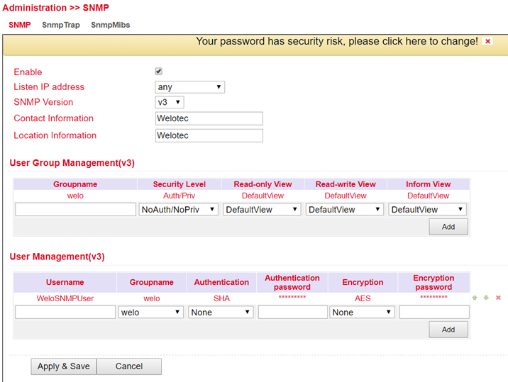
SNMP versions v1, v2c and v3 are supported.
SNMPv1 and SNMPv2 use the community name for authentication with read-only and read-write rights. The IP address under which the SNMP service is available can be selected under Listen IP address.
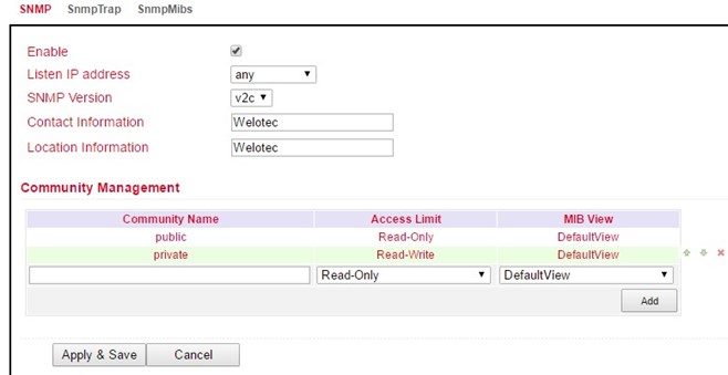
SNMPv3 supports user name and password for authentication. A group management is implemented. This is an advantage over the SNMPv1 and SNMPv2 versions, since here individual users can be specifically authorized for access (see following figure).
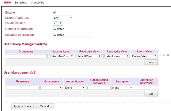
With SNMPv3, there is group and user management.
Authentication supports SHA or MD5.
Encryption supports AES or DES.
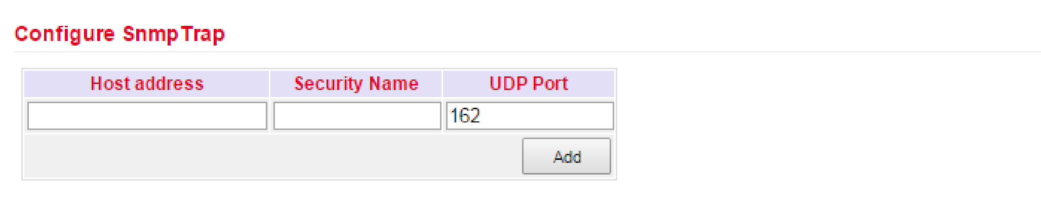
SnmpTrap
A SnmpTrap server can be entered. Here the router can actively send SNMP messages to the SNMP management server and does not wait until it receives an SNMP request from the management server.
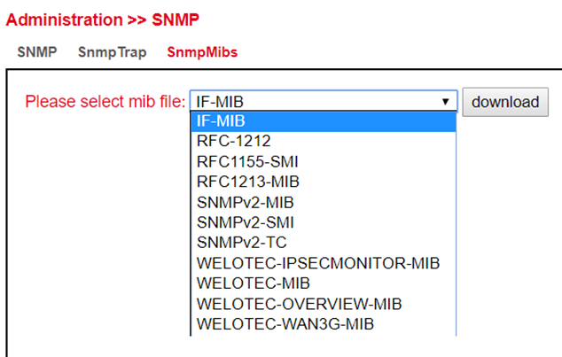
SnmpMibs
The SnmpMips for monitoring the router can be downloaded here and used for corresponding evaluations. Please select the desired MIB file and then click the download button.
Read SNMP Mibs using SNMPWALK.
1) Configure SNMP, such as shown below:
Read out the data entered above via SMTPWALK on e.g. a LINUX computer:
snmpwalk -v3 -u WeloSNMPUser -l AuthPriv -a SHA -A 123456789 -x AES -X 123456789 10.255.229.10
snmpwalk -v3 -u WeloSNMPUser -l AuthPriv -a SHA -A 123456789 -x AES -X 123456789 udp6:[2a02:d20:8:c01::1]
2) Download MIBS from TK800
3) Read MIBS (either via a LINUX computer or a common MIB browser)
mkdir -p .snmp/mibs cp Downloads/WELOTEC* .snmp/mibs/ after that the following MIBS are available:
WELOTEC-MIB
WELOTEC-OVERVIEW-MIB
WELOTEC-PORTSETTING-MIB
WELOTEC-SERIAL-PORT-MIB
WELOTEC-SYSTEM-MAN-MIB
WELOTEC-WAN3G-MIB
3) Start SNMPWALK (either via a LINUX computer or a common MIB browser)
snmpwalk -m +WELOTEC-MIB -v3 -u WeloSNMPUser -l AuthPriv -a SHA -A 123456789 -x AES -X 123456789 192.168.2.1 WELOTEC
WELOTEC-MIB::ihOverview.1.0 = STRING: “TK800”
WELOTEC-MIB::ihOverview.2.0 = STRING: “RF9151408241109”
WELOTEC-MIB::ihOverview.3.0 = STRING: “2011.09.r7903”
WELOTEC-MIB::ihOverview.4.0 = STRING: “1.0.0.r9919”
WELOTEC-MIB::ihWan3g.1.1.1.0 = INTEGER: 3
WELOTEC-MIB::ihWan3g.1.1.2.0 = INTEGER: 1
WELOTEC-MIB::ihWan3g.1.1.3.0 = Hex-STRING: 0B 00 00 00
WELOTEC-MIB::ihWan3g.1.1.4.0 = Timeticks: (149600) 0:24:56.00
WELOTEC-MIB::ihWan3g.1.1.5.0 = INTEGER: 11
WELOTEC-MIB::ihWan3g.1.1.6.0 = INTEGER: 2
WELOTEC-MIB::ihWan3g.1.1.7.0 = INTEGER: 0
WELOTEC-MIB::ihWan3g.1.1.8.0 = INTEGER: 2
WELOTEC-MIB::ihWan3g.1.1.9.0 = INTEGER: 21
WELOTEC-MIB::ihWan3g.1.1.10.0 = Counter32: 2698992
WELOTEC-MIB::ihWan3g.1.1.11.0 = Counter32: 35344140
WELOTEC-MIB::ihWan3g.1.2.1.1.0 = STRING: “860461024084629”
WELOTEC-MIB::ihWan3g.1.2.1.2.0 = STRING: “262010052709611”
WELOTEC-MIB::ihWan3g.1.2.1.3.0 = “”
WELOTEC-MIB::ihWan3g.1.2.1.4.0 = “”
WELOTEC-MIB::ihWan3g.1.2.1.5.0 = “”
WELOTEC-MIB::ihWan3g.1.2.2.1.0 = INTEGER: 0
WELOTEC-MIB::ihWan3g.1.2.2.2.0 = INTEGER: 0
WELOTEC-MIB::ihWan3g.1.2.3.1.0 = “”
WELOTEC-MIB::ihWan3g.1.2.3.2.0 = “”
WELOTEC-MIB::ihWan3g.1.2.3.3.0 = “”
WELOTEC-MIB::ihWan3g.1.2.3.4.0 = INTEGER: 0
WELOTEC-MIB::ihWan3g.1.2.3.5.0 = INTEGER: 0
WELOTEC-MIB::ihWan3g.1.2.3.6.0 = “”
WELOTEC-MIB::ihWan3g.1.2.4.1.0 = INTEGER: 0
WELOTEC-MIB::ihWan3g.1.2.4.2.0 = INTEGER: 0
WELOTEC-MIB::ihWan3g.1.2.4.3.0 = Gauge32: 0
WELOTEC-MIB::ihWan3g.1.3.1.1.0 = STRING: “262010052709611”
WELOTEC-MIB::ihWan3g.1.3.1.2.0 = STRING: “860461024084629”
WELOTEC-MIB::ihWan3g.1.3.2.1.0 = Gauge32: 0
WELOTEC-MIB::ihWan3g.1.3.2.3.0 = INTEGER: 0
WELOTEC-MIB::ihWan3g.1.3.2.4.0 = INTEGER: 0
WELOTEC-MIB::ihWan3g.1.3.2.5.0 = Gauge32: 193
WELOTEC-MIB::ihWan3g.1.3.2.6.0 = Gauge32: 0
WELOTEC-MIB::ihWan3g.1.3.3.1.0 = “”
WELOTEC-MIB::ihWan3g.1.3.3.2.0 = “”
WELOTEC-MIB::ihWan3g.1.3.3.3.0 = INTEGER: 1
WELOTEC-MIB::ihWan3g.1.3.3.4.0 = “”
WELOTEC-MIB::ihWan3g.1.3.3.5.0 = “”
WELOTEC-MIB::ihWan3g.1.3.3.6.0 = “”
WELOTEC-MIB::ihWan3g.1.3.3.7.0 = INTEGER: 0
WELOTEC-MIB::ihWan3g.1.3.3.8.0 = INTEGER: 0
WELOTEC-MIB::ihWan3g.1.3.3.9.0 = “”
WELOTEC-MIB::ihWan3g.1.3.4.1.0 = INTEGER: 0
WELOTEC-MIB::ihWan3g.1.3.4.2.0 = INTEGER: 0
WELOTEC-MIB::ihWan3g.1.3.4.3.0 = Gauge32: 0
Alarm
Status
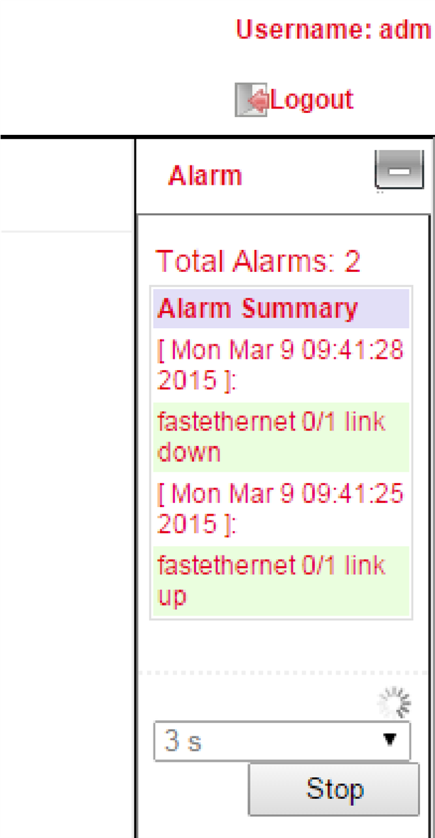
The alarm status shows an overview of the triggered alarms.
In this example, INFO message ID 1 shows that Fastethernet port 0/1 has been connected. ID 2 shows a warning message that the Fastethernet port 0/1 has been disconnected (Fig.1).

On the right side of the web interface you can see the alarm messages permanently regardless of which menu you are in (Fig. 2).
Alarm Input
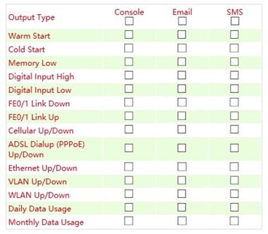
In the Alarm Input menu you define which alarm messages the router should output. By setting the checkmarks next to each entry, an alarm is activated or deactivated.
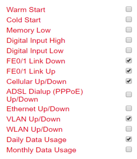
The following alarm messages are available.
Parameter |
Description |
|---|---|
Warm Start |
Warm start/reboot of the router |
Cold Start |
Cold start = booting the router if it was switched off or had no power before |
Memory Low |
Memory Low |
Digital Input High |
Digital Input High |
Digital Input Low |
Digital Input Low |
FE0/1 Link Down |
Fast Ethernet Port 0/1 disconnected |
FE0/1 Link Up |
Fast Ethernet Port 0/1 connected |
Cellular Up/Down |
Mobile connection GPRS/UMTS/LTE conected or disconnected |
ADSL Dialup (PPPoe) Up/Down |
ADSL Dialup connected or disconnected |
Ethernet Up/Down |
Ethernet connected or disconnected |
VLAN Up/Down |
VLAN connected or disconnected |
WLAN Up/Down |
WLAN connected or disconnected |
Daily Data Usage |
Displays the daily data used by the SIM card (only if the Data Usage function is activated, see Services > Data Usage) |
Monthly Data Usage |
Displays the monthly data used by the SIM card (only if the Data Usage function is activated, see Services > Data Usage) |
Alarm Output
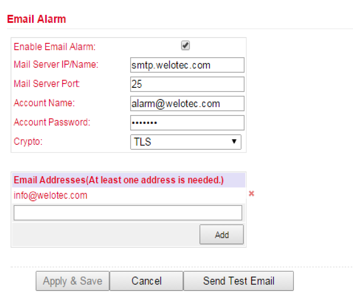
The Alarm Output menu is used to configure the e-mail server that will forward the alerts by mail.
If an alarm is triggered, a message is generated by the router and sent to the stored e-mail addresses via the specified e-mail server.
Parameter |
Description |
|---|---|
Enable Email Alarm |
Check the box for enabling/disabling the e-mail server functionality |
Mail Server IP/Name |
Host name (FQDN) or IP address of the e-mail server |
Mail Server Port |
Port of the mail server, default 25, but also 465 for SSL/TLS or 587 possible |
Account Name |
User account on the e-mail server through which the messages are to be sent |
Account Passwort |
Password of the user account on the e-mail server |
Crypto |
Encryption TLS |
Email Addresses |
E-mail address to which the mails are to be sent |
Alarm Map
On the Alarm Map you define whether the alerts should be displayed in the web browser or also sent by e-mail or SMS. Set the checkmark to Enable or Disable the feature.
Log
Log
The current messages of the router are displayed in the Log menu.
The log contains information about network, operational status, configuration changes, ISP connection information, IPSec, OpenVPN status and much more.
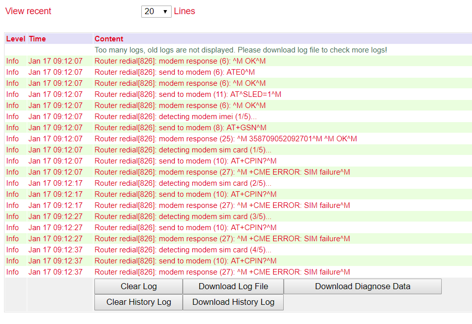
Under the log section there are options to clear the displayed logs, download the log, download the diagnostic file, clear the history and download the history.
Option |
Description |
|---|---|
Clear Log |
Delete displayed log files |
Download Log File |
Download log files |
Download Diagnose Data |
Download diagnostic data file |
Clear History Log |
Delete log history |
Download History Log |
Log history download |
System Log
In System Log you can specify a syslog server to which the logs should be sent over the network.
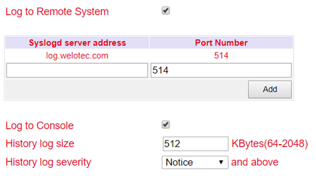
Under Syslog server address the host name of the syslog server (FQDN) or the IP address is specified. Port 514 is the default port for syslog servers.
Cron Job
Under Time Schedule you can have actions executed on the router at specific times, such as a reboot of the router. Here you could always reboot the router at a certain time.
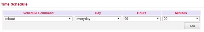
Under Time Schedule you can select the schedule command (currently only reboot). With Day you select daily (everyday) and with Hours and Minutes you control the start time. Click on the Add button to apply the settings.
Upgrade
Firmware updates of the router can be performed in the Upgrade menu. A firmware update can contain new functions or also eliminate errors. The installed firmware is displayed under the Select the file to use field.
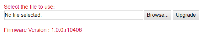
Under Browse you select the firmware file which you have downloaded before (this must be unpacked either as *.bin or *.pkg file). By clicking on Upgrade the firmware will be installed on the router.
Please note that the bootloader and the IO board may have to be updated separately if the firmware version is significantly older. If you have any questions, please contact our support.
Reboot
The router is restarted with Reboot.
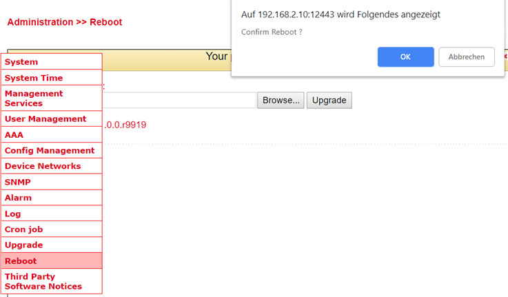
By clicking OK you confirm the restart of the router.
Save the configuration of the router before you restart the router. Otherwise, the configuration may be lost when you restart.
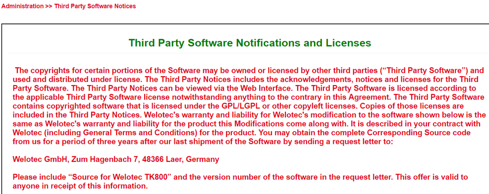
Third Party Software Notices
Here are the software terms and licenses from all third-party vendors related to the TK800 router series.
Network
Cellular
Cellular is the mobile communication interface of the router. If a SIM card is inserted in the router, you can dial into the Internet via GPRS, EDGE, UMTS or LTE, depending on the router model.
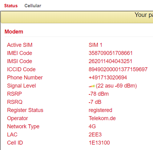
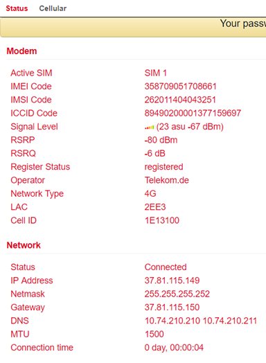
Cellular Status
Under Status there is an overview of the current status (Connected or Disconnected).
The Network Type in the Status tab and the IP address in the Network area is the deciding factor. In the Modem area you can also see the signal level, RSRP and RSRQ.
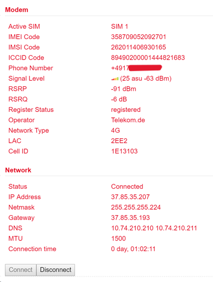
Under certain circumstances, the router may not be assigned the correct DNS server by the provider. Check whether there is no entry under DNS or an entry such as 10.74.210.210 (Telekom).
The RSRP value is one of the most important values when it comes to assessing one’s own reception value or reception quality. It is measured directly by the terminal device. The RSRP is also used to determine the currently strongest radio cell in the vicinity.
SRP |
School Grade |
Comment |
|---|---|---|
-50 bis -65 dBm |
1 (very good) |
excellent reception is available - perfect! |
-65 dBm bis -80 dBm |
2 (good) |
good, sufficient reception conditions |
-80 dBm bis -95 dBm |
3 (satisfactory) |
not perfect but sufficient for stable connections |
-95 dBm bis -105 dBm |
4 (sufficient) |
still acceptable conditions with speed restrictions; possibly also interruptions |
-110 dBm bis -125 dBm |
5 (poor) |
very poor level - urgent need for action; probably hardly any connection possible |
-125 dBm bis -140 dBm |
6 (insufficient) |
extremely poor - probably no connection possible |
The RSRQ is a calculated ratio value that results from the value for RSRP and the RSSI. It is enormously important for evaluating an LTE connection and the reception quality. The analysis of this value is indispensable for the optimal alignment of antennas for stationary use of LTE. Together with the RSRP, this enables the user to find the optimal position and alignment for his equipment (e.g. [antenna]).
RSRQ |
School Grade |
Comment |
|---|---|---|
-3 dB |
1 (very good) |
optimal connection quality, no interference from disruptors |
-4 … -5 dB |
2 (good) |
disruptive influences are present, but have no impact |
-6 … -8 dB |
3 (satisfactory) |
interfering influences, slight influence on the connection |
-9 … -11 dB |
4 (sufficient) |
disruptive interference, noticeable influence on the connection |
-12 … -15 dB |
5 (poor) |
heavy interference present, connection very unstable |
-16 … -20 dB |
6 (insufficient) |
extremely disruptive interference, no usable connection possible |
Most providers assign private IP addresses or IP addresses that are not routed via the Internet. A successful or unsuccessful ping does not indicate whether the IP address of the router can really be reached.
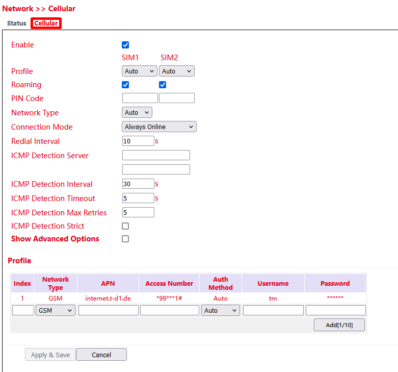
Cellular Configuration
Under Network > Cellular > Cellular you can change access settings for the cellular network.
Parameter |
Description |
Factory settings |
|---|---|---|
Enable |
Enable or disable the cellular connection |
Enabled |
Profile |
APN profile for SIM card 1 and SIM card 2 |
Auto / Auto Automatic selection of APN based on SIM card |
Roaming |
Enable or disable whether the SIM card should allow roaming. |
Enabled / Enabled |
PIN Code |
PIN code for the SIM card. |
Blank / Blank |
Network Type |
Selection: Auto (automatic network selection), 2G (GPRS / EDGE), 3G (UMTS, HSDPA, HSUPA, HSPA+), 4G (LTE) |
Auto |
Connection Mode |
Select whether the router should always be connected to the cellular network or only dial in when needed. |
Always Online |
Redial Interval |
Redial interval |
10 seconds |
ICMP Detection Server |
Up to two ICMP detection servers can be entered here to monitor the connection. |
blank |
ICMP Detection Interval |
Interval at which the ICMP Detection Server checks the Internet connection. |
30 seconds |
ICMP Detection Timeout |
ICMP timeout or ping timeout. Maximum time that the ping may take (Round Trip Time). |
5 seconds |
ICMP Detection Max Retries |
Number of retries on failed ICMP ping. |
5 |
ICMP Detection Strict |
If disabled, the ICMP ping is sent only when no data is sent or received. |
Disabled |
Show Advanced Options |
When enabled, more configuration options become visible. |
Disabled |
Connect on Demand
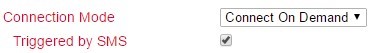
Here you have to set the checkmark at Triggered by SMS. The router will only connect to the Internet if it has received the command to do so via SMS beforehand.
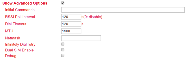
Show Advanced Options
Parameter |
Description |
Factory settings |
|---|---|---|
Initial Commands |
Start commands e.g. if Triggered by SMS is selected or special AT commands are to be used. |
blank |
RSSI Poll Interval |
Polling interval of the signal strength |
120 seconds |
Dial Timeout |
Maximum time for the dial-up attempt |
120 seconds |
MTU |
Maximum size of a package |
1500 bytes |
Netmask |
An additional netmask can be entered here |
blank |
Infinitely Dial Retry |
If Triggered by SMS is selected, the dialing can be set to infinite here |
off |
Dual SIM Enable |
Enable/disable the dual SIM option. If this option is activated, special selection fields are available (see below) |
disabled |
Main SIM |
The main sim card that will be used |
SIM1 |
Max Number of Dial |
Maximum connection attempts, then restart of the modem |
5 |
Min Connected Time |
Minimum connection time |
0 seconds |
CSQ Threshold |
Minimum signal strength SIM1 / SIM2 |
0 |
CSQ Detect Interval |
Interval for signal strength query SIM1 / SIM2 |
0 seconds |
CSQ Detect Retries |
Repeat attempts for signal strength query SIM1 / SIM2 |
0 |
Backup SIM Timeout |
Time after which it is switched back to the main SIM card |
0 Sekunden |
Debug |
If enabled, more detailed logging is done |
disabled |
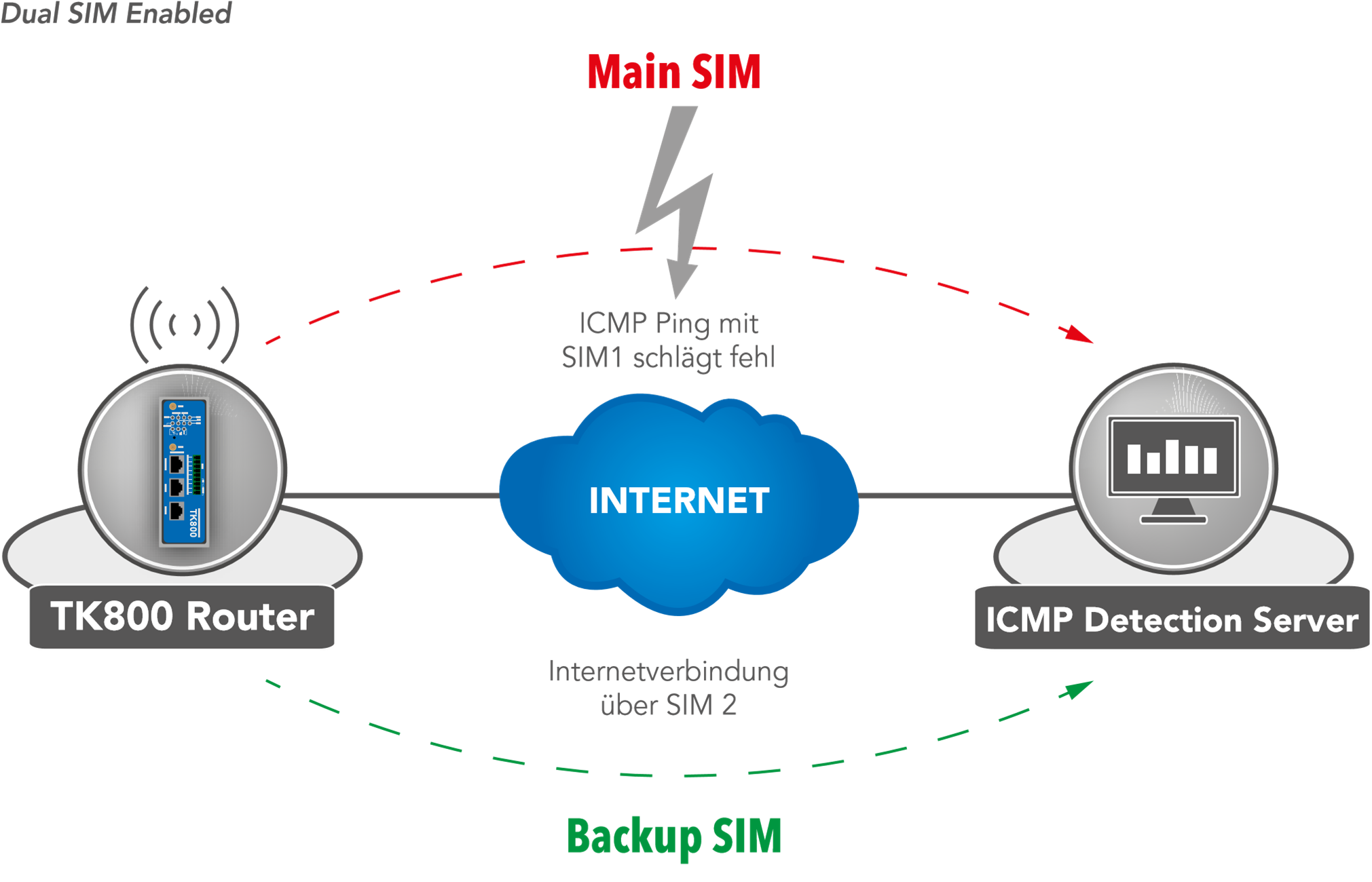
If a provider is unavailable, the system switches to the alternative provider. The same applies when the mobile data volume is used up. The TK 800 uses ICMP to monitor the data connection. If this is no longer available (because the ping fails), the router switches to the other connection.
Ethernet
In the Ethernet area, you have the option to make settings for the network ports. Depending on the model, you can adjust the interfaces individually. It is important to know that the router models have a network interface with the designation FE 0/1 and a network bridge, which is designated FE 1/1 to 1/4 depending on the model.
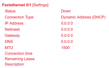
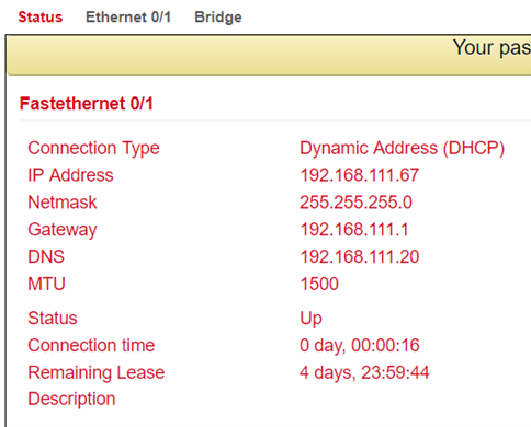
Ethernet Status
The status page shows the current status of the network ports (depending on the model).
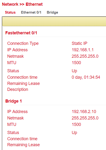
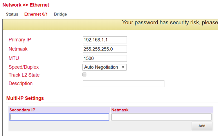
Fast Ethernet 0/1
Here you can adjust the settings of the network interface with the label FE 0/1.
Parameter |
Description |
Factory settings |
|---|---|---|
Primary IP |
Primary IP address can be entered and changed here |
192.168.1.1 |
Netmask |
Subnet mask |
255.255.255.0 |
MTU |
Maximum Transmission Unit = maximum size of an unfragmented data packet |
1500 |
Speed/Duplex |
Five options are available: Auto Negotiation: automatic negotiation of speed 100M full-duplex: 100 megabits full-duplex 100M half-duplex: 100 megabits half-duplex 10M full-duplex: 10 megabits full-duplex 10M half-duplex: 10 megabits half-duplex |
Auto |
Track L2 State |
Checkmark set: Port status remains administratively disconnected after being disconnected (Down) Checkmark not set: Port status reconnects after being disconnected (UP) |
Checkmark not set |
Description |
Description of the port - Freely selectable name |
- |
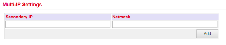
In the lower menu additional IP addresses can be assigned for the FastEthernet 0/1 port.
The configuration as DHCP client is described under DHCP. The configuration of a WAN interface is described under Wizard.
Bridge (TK8x5-EXW)
Overview of the existing bridge. Only one bridge is possible!

If you delete the bridge, no more IP address is set on the interfaces FE1/1 - FE1/4. The router is then only accessible via FE0/1 or console!!!
To edit the bridge, select the existing entry and then click Modify.
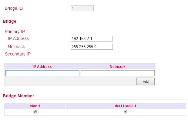
Bridge:
Here you can change the IP address of the bridge. Under Secondary IP you can assign additional IP addresses to the bridge.
Bridge Member:
The interface dot11radio1 is the WLAN interface. Via the hooks a bridge member can be added or removed from the bridge.
Removing a bridge member from the bridge results in the IP address of the interface being empty. It is therefore recommended to only make changes via the interface FE0/1, as this is not a bridge member.
VLAN (TK8x5-x)
A Virtual Local Area Network (VLAN) is a logical subnet within a switch or an entire physical network. A VLAN separates physical networks into subnets by ensuring that VLAN-capable switches do not forward the frames (data packets) of one VLAN to another VLAN. This happens even though the subnets may be connected to the same switches.
VLAN Trunk
In the VLAN Trunk menu, different VLAN IDs can be assigned to the FastEthernet 1/1 to 1/4 network ports.
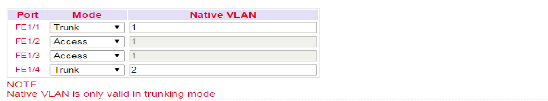
The options Access and Trunk are available for the FastEthernet ports.
In Access Mode, VLAN 1 is always selected.
In Trunk Mode, you can assign VLAN IDs between 1-4000 to the FastEthernet ports.
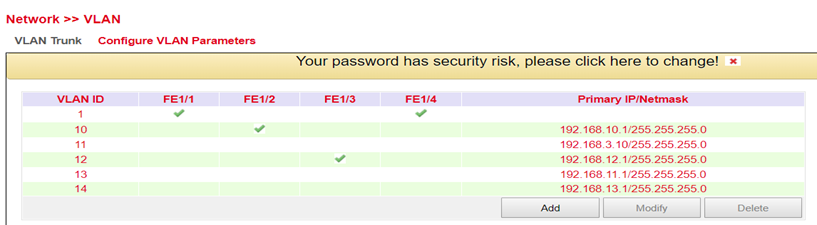
Configure VLAN Parameters
In the Configure VLAN Parameters menu you can change the assignment of VLANs to FastEthernet ports and create new VLANs.
Button |
Description |
|---|---|
Add |
A new VLAN can be added via the Add button. |
Modify |
The existing VLANs can be edited by selecting them and then clicking on Modify. |
Delete |
With Delete a previously selected VLAN can be deleted. |
Adding a new VLAN:
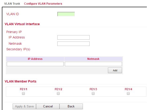
Assign a new VLAN ID (e.g. 3) and then a Primary IP address. If required, multiple IP addresses can be entered under Secondary IP(s) (confirm with Add after each addition).
Under VLAN Member Ports, one or more FastEthernet port/s are assigned to the VLAN by checking the checkbox.
The TK800 series routers do not have a built-in ADSL modem. For the use of ADSL Dialup, an external ADSL modem must be connected to the WAN port.
ADSL Dialup (PPPoE)
Status
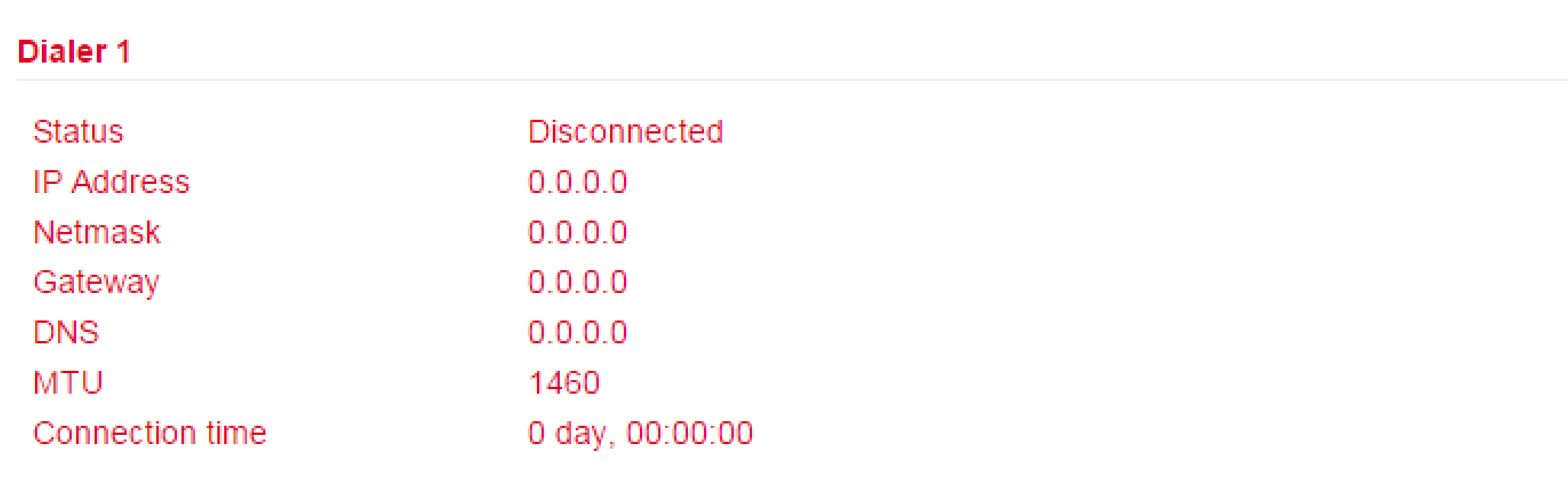
The TK800 series routers do not have a built-in ADSL modem. For the use of ADSL dialup, an external ADSL modem must be connected to the WAN port. For the digital transmission technology, an appropriate DSL modem that supports the new IP technologies is required.
ADSL Dialup (PPPoE)
Here you can configure the dial-in via the DSL modem for PPPoE. The TK800 does not have its own DSL modem, so these cannot dial in independently.
In this case, an appropriate DSL modem that can handle the new IP technologies is required. The modem should meet the following criteria:
VDSL2/ADSL2 Ethernet-Modem
Annex A/B/M/J compatible
PPPoE bridge operation
IPv4 and IPv6 compatible
DSL standards
ANSI T1.413 Issue 2
ITU G.992.1 A/B (G.dmt)
ITU G.992.2 (G.lite)
ITU G.992.3 (VDSL2)
ITU G.992.4 (G.HS)
ITU G.992.5 (ADSL2+)
You should therefore ensure that the modem is connected to the router before you start the configuration. The DSL modem should be connected to the FE 0/1 interface or to a defined VLAN port.
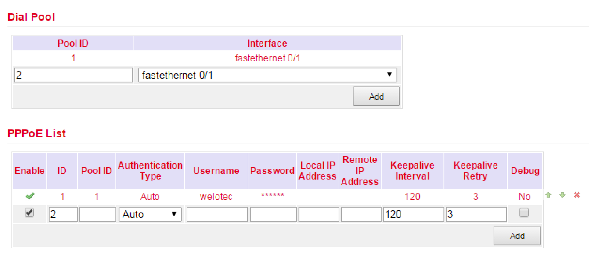
Dial Pool
The Pool ID is used to define the Interface for the PPPoE dial up.
PPPoE List
Parameter |
Description |
|---|---|
Enable |
Enables or disables the PPPoE entry |
ID |
Assign any unique ID |
Pool ID |
The pool ID previously created via Dial Pool for the interface via which the connection is to be established. |
Authentication Type |
Auto, PAP, CHAP can be selected. In most cases this parameter can be set to Auto. |
Username |
The username you received from your provider for dial-up. |
Password |
The password you received from your provider for dial-up. |
Local IP Address |
Your local IP address |
Remote IP Address |
IP address of the remote device (modem) |
Keepalive Interval |
Time after which the connection should be checked. |
Keepalive Retry |
Number of attempts when a connection check fails. |
Debug |
Detailed logging is performed when activated. |
The wizard can also be used to set up a PPPoE connection via New WAN. This is easier than the manual configuration!
WLAN (TK8x5-EXW)
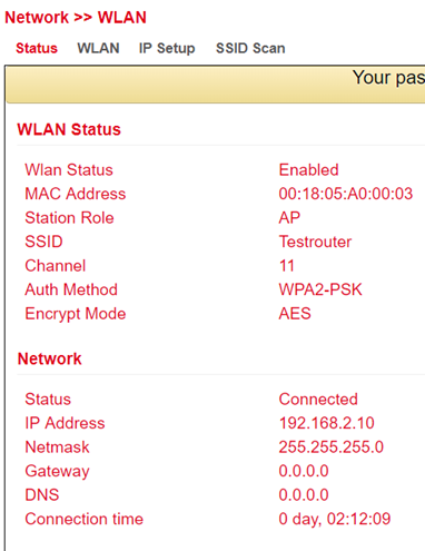
WLAN Status
Under Network > WLAN you can first view the status of the WLAN.
For example, the current SSID of the router, the IP address or the role of the WLAN module (access point or client) can be read here.
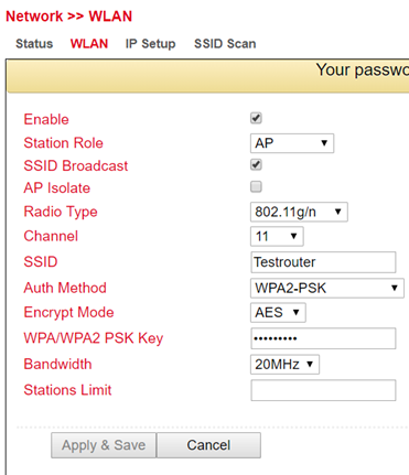
WLAN Configuration
Under Network > WLAN > WLAN you can configure the WLAN.
Parameter |
Description |
Factory settings |
|---|---|---|
Enable |
Enables or disables the WLAN |
Disabled |
Station Role |
AP (Access Point), Client or AP Client |
AP |
SSID Broadcast |
Display the SSID if it is supposed to be visible |
Enabled |
AP Isolate |
Enables or disables AP isolation |
Disabled |
Radio Type |
The radio standard can be selected here |
802.11g/n |
Channel |
The radio channel can be selected here |
11 |
SSID |
The SSID that identifies your WLAN and will be displayed when searching for WLAN networks. |
TK800 |
Auth Method |
The encryption standard to be used. OPEN, if the WLAN is not to be protected (not recommended). |
OPEN |
Encrypt Mode |
If Open or Shared is selected: WEP40 or WEP104, both are actually no longer used today because they are not secure. When selecting the other options TKIP or AES |
NONE |
Bandwidth |
20MHz or 40MHz channel bandwidth. A larger channel bandwidth can increase the speed, but there are fewer overlap-free channels. |
20MHz |
Stations Limit |
Maximum number of simultaneously connected clients |
blank |
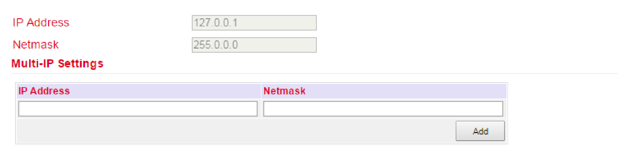
IP Setup
Under Network > WLAN > IP Setup the IP address of the WLAN interface can be changed.
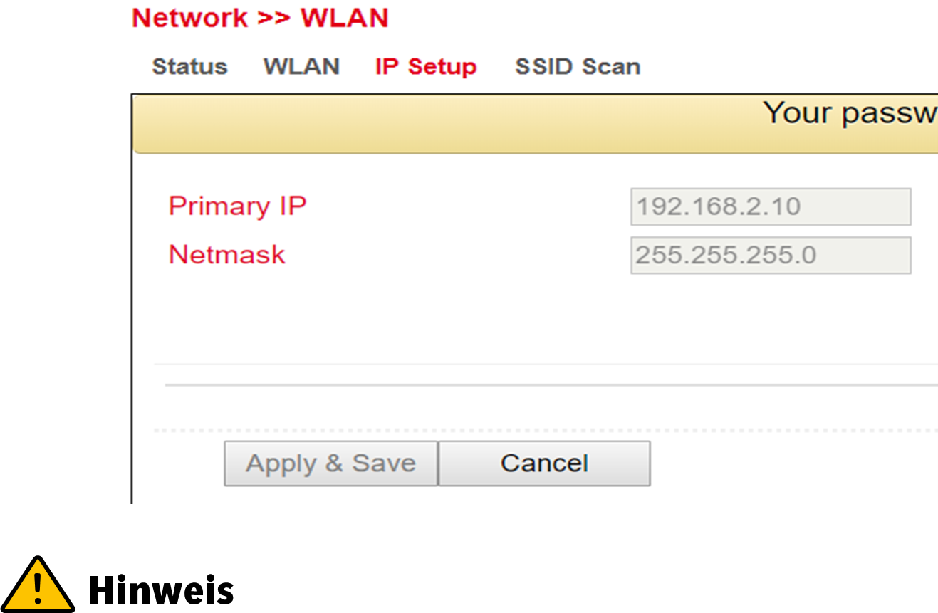
The IP address can only be changed if the WLAN interface is not a bridge member.
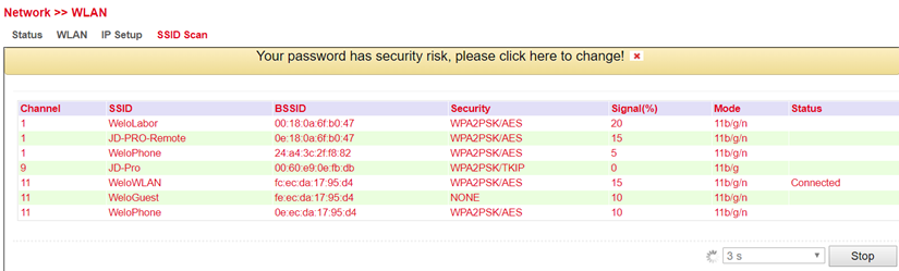
SSID Scan
Under Network > WLAN > SSID Scan you can search for available WLAN networks. If you have configured the TK 800 as a WLAN client, it is possible to scan the WLAN networks within range for their SSID at this point. If the TK 800 is connected to a WLAN as a client, this is indicated in the status with Connected.
Loopback
Loopback Configuration
Under Network > Loopback you can enter further loopback IP addresses. The default loopback IP address 127.0.0.1 cannot be edited.
Services
DHCP
The Dynamic Host Configuration Protocol (DHCP) is a communication protocol in computer technology. It allows the assignment of the network configuration to clients by a server.
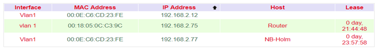
DHCP Status
Under Services > DHCP > Status you can see who is currently connected to the router via which interface.
DHCP Server
Under Services > DHCP > DHCP Server you can configure settings for the DHCP server. Select the appropriate interface and enter the start or end IP address and the lease, see example.
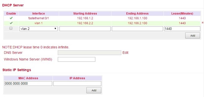
With Static IP Settings an IP address can be assigned to a specific MAC address.
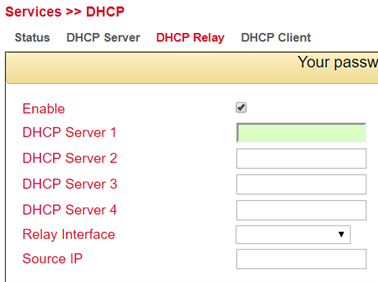
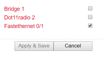
DHCP Relay
Under Services > DHCP > DHCP Relay you can specify remote DHCP servers, which then take over the DHCP management for the networks connected to the router. By clicking Enable, you activate this function.
DHCP Client
Under Services > DHCP > DHCP Client the router itself can receive a DHCP address from a DHCP server. To do this, select the interface that is to be configured via DHCP. The interfaces can vary depending on the router model.
DNS
The Domain Name System (DNS) is one of the most important services in many IP-based networks. Its main task is to answer name resolution requests.
The DNS works similar to a telephone directory assistance. The user knows the domain (name of a server on the Internet), e.g. welotec.com, and sends this as a request to the Internet. The domain is then converted by the DNS into the corresponding IP address (if you like, the “connection number” on the Internet). E.g. an IPv4 address of the form 192.168.2.1 and thus leads to the correct server.
DNS Server
Under Services > DNS > DNS Server you can enter two DNS servers. These are then valid for all interfaces, unless a different DNS server was assigned via DHCP.

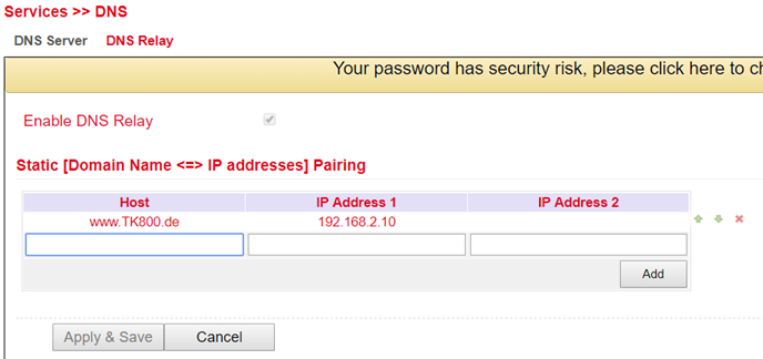
DNS Relay
Under Services > DNS > DNS Relay you can also enter DNS resolutions manually. Click Add to add the entry and Apply & Save to apply it.
DDNS
Dynamic DNS or DDNS is a technique to dynamically update domains in the Domain Name System (DNS). The purpose is that a computer (e.g. a PC or a router) automatically and quickly changes the associated domain entry after changing its public IP address. This way the computer is always reachable under the same domain name, even if the current IP address is unknown to the user. Common providers for this service are e.g. DynDNS or NoIP.
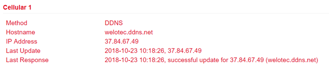
DDNS Status
Under Services > DDNS > Status the currently used DDNS services are displayed.
DDNS
Under Services > DDNS > DDNS you can add a new DDNS service. It is important that a new DDNS service is created under DDNS Method List first.
Afterwards you have to assign it to an interface, this is done under Specify A Method To Interface.
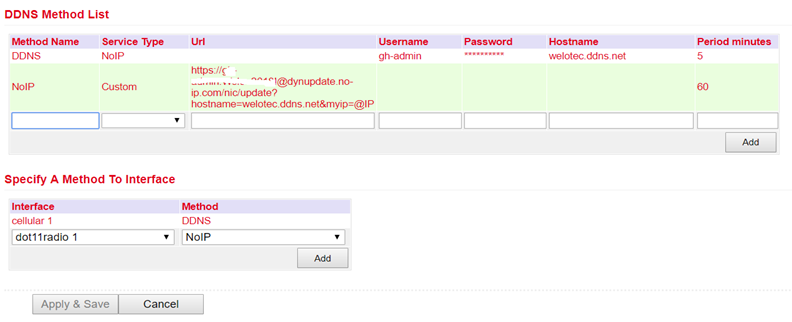
DDNS Method List |
|
|---|---|
Method Name |
Freely selectable name for the service. |
Service Type |
The most common DDNS services are listed here. If the DDNS service is not listed, an individual DDNS service can be used via Custom. |
Url |
Only used for the selection Custom at Service Type. The complete url of the DDNS service including username and password is entered here, e.g. for NoIP https://username:password@dynupdate.no-ip.com/nic/update?hostname=welotec.ddns.net&myip=@IP The @IP parameter always updates the assigned IP address. |
Username |
The user name for the DDNS service is entered here. |
Password |
The password for the DDNS service is entered here. |
Hostname |
The name of the domain that is being used. |
Period minutes |
Specifies how often an update of the IP address is to be performed. Input values can be entered from 1 to 999999 minutes. |
Specify A Method To Interface |
|
|---|---|
Interface |
The interface of the router whose IP address should be accessible via the DDNS service. |
Method |
A DDNS service previously created under DDNS Method List. |
You need an account of a DDNS provider, which you have to configure before. This account may be chargeable, depending on the provider.
SMS
Introduction
The TK800 can be reached from outside via SMS and reacts to various commands sent via SMS. Thus, it is possible to query the status of the device, start / stop dial-up or restart the device.
Status query / restart
Go to the SMS subitem via the Services menu item
Click the Enable checkbox to turn on the feature
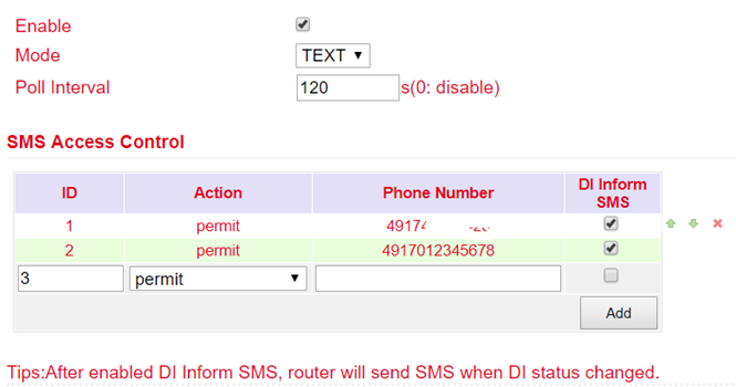
Enter in the table SMS Access Control the phone numbers which are allowed to send SMS to the router (format 4917123456789, no 0049 or +49!) and enter permit as action
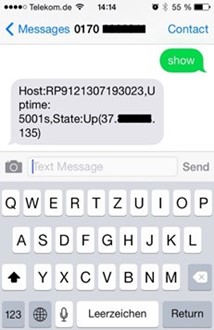
If an SMS with the content show is now sent to the mobile phone number of the router, the router sends its current status as a reply
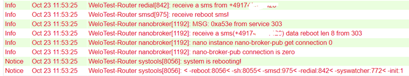
If an SMS with the content reboot is sent to the router, it restarts. You can also follow this process in the router’s log.
Connecting or disconnecting from the Internet
After successful configuration, you can also control the router’s Internet connection via SMS. However, this requires that the router is set to “Connect On Demand”!
Go to the Network menu item and select the Cellular subitem.
Now select the Cellular tab
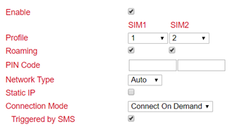
Select the Connect On Demand mode here under Connection Mode and activate the Triggered by SMS field. Now you can send the following commands to the router via SMS:
disconnects the Internet connection (see fig.)
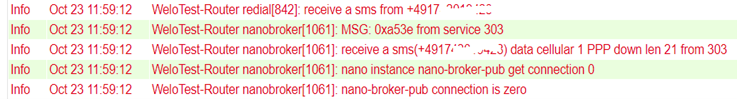
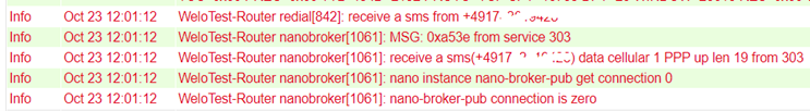
cellular 1 ppp up - restores the Internet connection (see fig.)
Switch digital relay on or off
Another important SMS command is to switch the digital relay on or off via SMS.
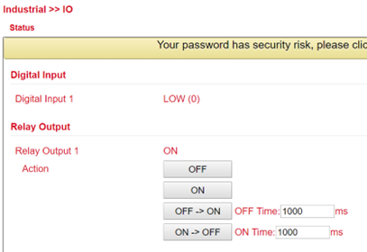
The following SMS commands can be used for this
io output 1 on - switches on the relay
io output 1 off - switches the relay off
GPS (TK8x5L-EGW bzw. TK8x5L-EDW)
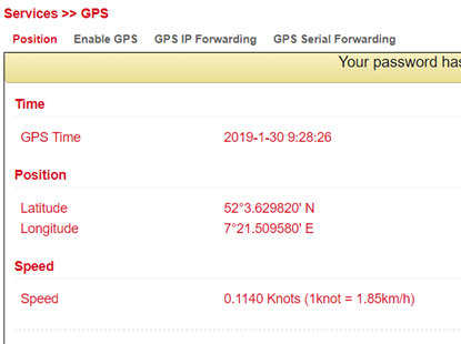
Position
Under Services > GPS > Position you will see the data about the current position if the corresponding antenna is connected to the router.
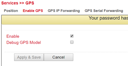
Enable GPS
To enable the GPS function of the router open the menu under Services > GPS > Enable GPS and click on the checkbox Enable to switch on the function. With Apply & Save you save the settings and enable the GPS.
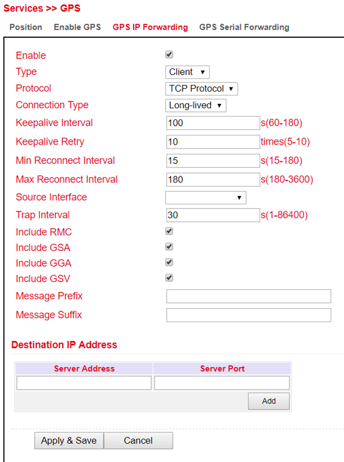
GPS IP Forwarding
Open the menu under Services > GPS > GPS IP Forwarding and click the Enable checkbox to turn on the function. This function is only available if the Debug GPS Model (from the previous chapter) is disabled. Here you can now make the appropriate settings. With Apply & Save you save the settings and activate them.
GPS IP Forwarding List |
|
|---|---|
Type |
Selection between client and server |
Protocol |
Here you can choose between the protocol types TCP or UDP. |
Connection Type |
Selection between long-lived and short-lived is possible. Standard is Long-lived |
Keepalive Interval |
Entry between 60 and 180 seconds possible. Default = 100s. |
Keepalive Retry |
The number of repetitions here may be between 5 and 10 times. Standard = 10 |
Min Reconnect Interval |
Min. reconnection interval between 15 and 180 seconds. Default = 15s. |
Max Reconnect Interval |
Min. reconnection interval between 180 and 3600 seconds. Default = 180s. |
Source Interface |
Selection of the corresponding interface that is to be redirected to |
Trap Interval |
The interval may be between 1 and 86400 seconds. Default = 30 |
Include RMC |
Recommended minimum data set. When selected, the minimum of the GPS receiver is output |
Include GSA |
Active satellites. Information about PRN numbers of the satellites whose signal is used for position determination is output here. |
Include GGA |
Most important data set with time, position, height and quality of the measurement |
Include GSV |
Visible satellites. Provides information about satellites that can possibly be received at present and information about their position, signal strength, etc. Since only the information of four satellites can be transmitted per record (limitation to 82 characters), there can be up to three such records |
Message Prefix |
Input of a message prefix possible. Free input |
Message Suffix |
Input of a message suffix possible. Free input |
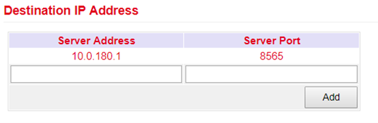
Entering a destination address for a server is possible at this point.
GPS Serial Forwarding
Open the menu under Services > GPS > GPS Serial Forwarding and click on the Enable checkbox to switch on the function. Here you can now make the appropriate settings. With Apply & Save you save the settings and activate them.
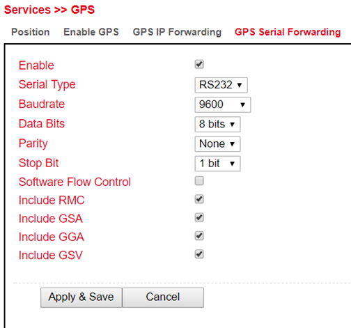
GPS Serial Forwarding List |
|
|---|---|
Serial Type |
Selection of the serial interface. RS232 or RS485. |
Baud rate |
Here the transmission rate can be selected. Value between 300 and 230400 possible. Default = 9600 |
Data Bits |
Setting of the data bits. Selection between 7 bits and 8 bits. Default = 8 bits |
Parity |
Here the parity for the interface can be set. Default = none |
Stop Bit |
Setting of the stop bits. Default = 1 bit |
Software Flow Control |
Can be switched on or off. Default = off |
Include RMC |
Recommended minimum data set. When selected, the minimum of the GPS receiver is output |
Include GSA |
Active satellites. Information about PRN numbers of the satellites whose signal is used for position determination is output here. |
Include GGA |
Most important data set with time, position, height and quality of the measurement |
Include GSV |
Visible satellites. Provides information about satellites that can possibly be received at present and information about their position, signal strength, etc. Since only the information of four satellites can be transmitted per record (limitation to 82 characters), there can be up to three such records |
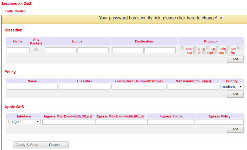
QoS
At this point the definition of Quality of Service is possible. Select Services > QoS.
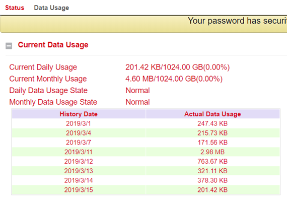
Data Usage
In this area you can see the consumption of your data if you have configured this under Data Usage. Select Services > Data Usage.
Data Usage
Open the menu under Service > Data Usage and Data Usage. Now check the Monitoring box to activate this section. Now enter your data.
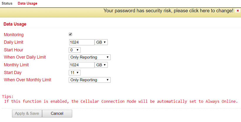
Data Usage |
|
|---|---|
Monitoring |
Activate your data consumption display here |
Daily Limit |
Enter a guideline value for the daily limit here. Data can be entered in KB, MB or GB. |
Start Hour |
Time at which the measurement is to be started. |
When Over Daily Limit |
Here you can enter what should happen when the entered limit is reached or exceeded. Options are: Only Reporting Here, only the consumption value is displayed Stop Forward Here, the further consumption of data is stopped Shutdown Interface Here, the interface is switched off. |
Monthly Limit |
Enter an approximate value for the monthly limit here. Data can be entered in MB or GB. |
Start Day |
Select here the day on which the measurement for the monthly limit should start |
When Over Monthly Limit |
Here you can enter what should happen when the entered limit is reached or exceeded. Options are: Only Reporting Here, only the consumption value is displayed Stop Forward Here, the further consumption of data is stopped Shutdown Interface Here, the interface is switched off. |
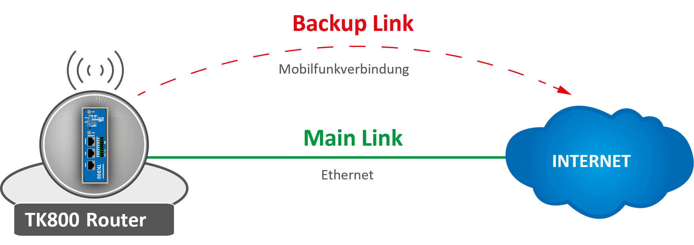
Link Backup
With the TK800, it is possible to use two different Internet connections (wired and cellular) to increase accessibility.
The router periodically checks the primary Internet connection and automatically switches to the secondary Internet connection in case of failure. As soon as the primary Internet connection is available again, the router automatically switches back to this connection.
In this example, a wired (Ethernet, DHCP) is used as the primary Internet connection and cellular (4G LTE) as the secondary.
Configuring a WAN Port – Modify Bridge (TK8X2-X only)
The prerequisite for Link Backup is Internet access via the cellular network. Therefore, configure the mobile network interface (Cellular) accordingly to be able to connect to the Internet. The router is preconfigured for T-Mobile SIM cards, so no configuration steps are usually necessary here.
On the TK8X2-X, the two Ethernet ports are connected via a bridge at the factory. To configure one of the ports to the WAN port, the corresponding port must be excluded from the bridge.
To do this, perform the following steps:
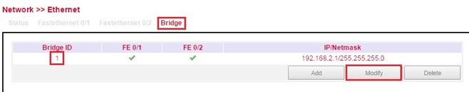
Go to the subitem Ethernet via the subitem Network.
Now select the Bridge tab
Click here in the line with the Bridge ID 1 and edit the entry by clicking Modify.
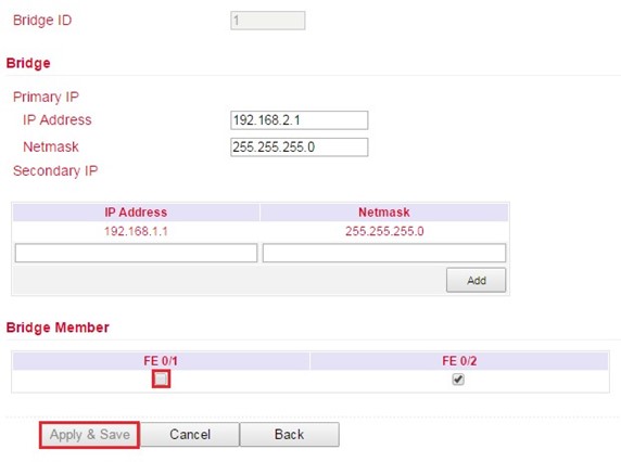
Remove the check mark for the interface FE 0/1 and confirm the change with Apply & Save.
Configuring a WAN port
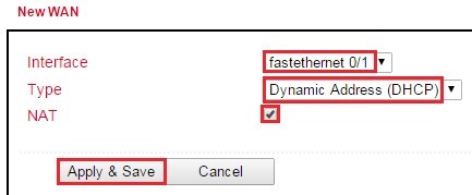
In this manual the port FE 0/1 is defined as WAN port. The New WAN Wizard is used for this purpose.
In the Wizard menu, a new WAN port can be configured via the subitem New WAN
as interface the Ethernet port (FE 0/1) currently detached from the bridge is specified, exemplary DHCP is also used for the port
NAT must be activated if the connected devices are to establish a connection to the Internet
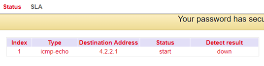
in the next step the ICMP program (SLA) is configured
Under IP Address (Destination Address) a pingable IP address with high availability should be entered (Note: In this example 4.2.2.1 was entered, since this address has a very high availability)
all other data can be copied from the example
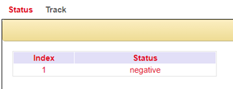
the just created SLA program is monitored with the help of tracking to be able to register an interruption of the main line
this is configured as shown in the following example
to define which one acts as the main line and which one acts as the backup line, the backup interface is set up
this is configured as shown in the following example
Description of the Configuration Elements:
Main Interface |
primary line to be monitored |
|---|---|
Backup Interface |
secondary line, which is used in case of failure of the primary line |
Startup Delay |
switch-on delay of the interface monitoring |
Up Delay |
switching delay |
Down Delay |
switching delay |
Track ID |
Reference to ICMP monitoring |
In the last step, the routing entries are created or adjusted as in the following example. It is important that the distance of the main line (here: FE 0/1) has a smaller value than that of the backup line. With the TrackID, the main line is bound to the ICMP monitoring that was created in the previous step Description of the configuration elements:
Destination |
Destination address where to be routed |
|---|---|
Netmask |
Subnet mask belonging to the destination address |
Interface |
Interface via which to send |
Gateway |
IP address via which to send |
Distance |
Route preference/cost |
Track ID |
Reference to ICMP monitoring |
Main line works (Internet connection via WAN)
If the main line is working and an Internet connection is established through it, the following can be seen:
SLA-Status
Track-Status
Status of the cellular connection
Status of the WAN connection (Ethernet)
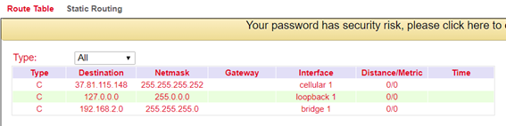
Routing table
Main line does not work (Internet connection via cellular radio)
If the main line is not working and an Internet connection is established via the cellular interface, the following can be seen:
SLA-Status
Track-Status
Status of the cellular connection
Routing table
SLA
SLA monitoring monitors the connections to peers within a network structure. Ping tests to defined destinations provide information about the availability of the peers and show the state of the line in the status (up or down).
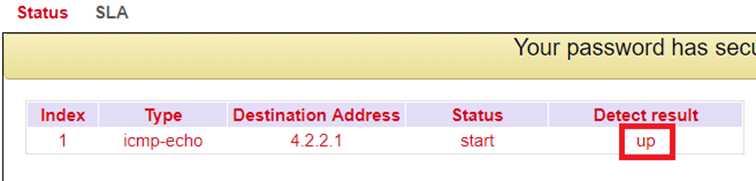
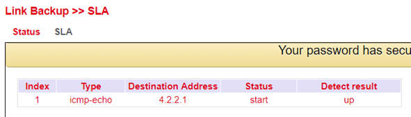
Status
The SLA status indicates whether the ping attempt is successful (Detect result up) or unsuccessful (Detect result down).
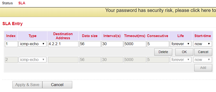
SLA Configuration
Enter the desired data under Link Backup > SLA > SLA to monitor the status of the line.
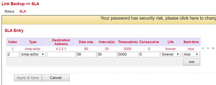
Parameter |
Description |
|---|---|
Index |
Freely selectable, used to identify the entry. |
Type |
icmp-echo, a simple ping to check the connection. |
Destination Address |
The address that will be pinged. It should be highly available if possible, e.g. a Google DNS server (8.8.8.8). |
Data size |
The packet size of a ping, usually 56 bytes. |
Interval(s) |
The time interval in seconds at which the ping is executed. |
Timeout(ms) |
Timeout for a ping. |
Consecutive |
Number of retries, in case of a failed ping. |
Life |
forever, the ping should always be executed. |
Start-time |
now, the check should start immediately. |
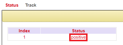
Track
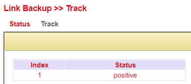
Status
Displays the Track status, positive means that the ping attempt is successful or the interface is connected to the Internet. You can view the track status via Link Backup > Track > Status if it has been configured.
Track Configuration
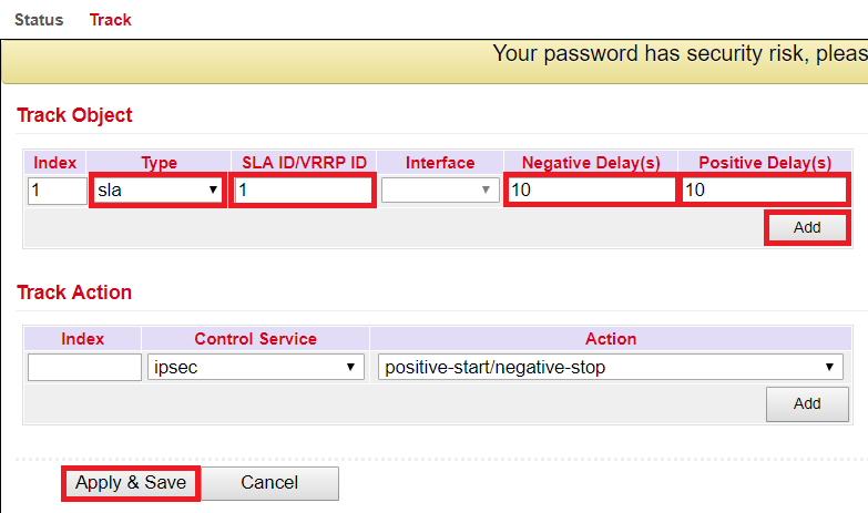
Set up your track object under Link Backup > Track > Track.
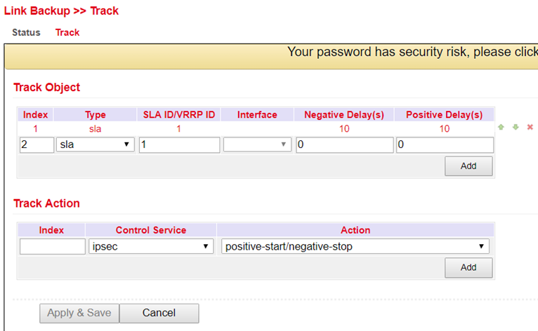
Parameter |
Description |
|---|---|
Index |
Freely selectable. Used to identify the entry. |
Type |
SLA or interface. |
SLA ID |
Index, the SLA that was previously created. |
Interface |
Not used with SLA. |
Negative Delay(s) |
Delay when switching to the backup interface if the Internet connection on the main interface is lost. |
Positive Delay(s) |
Delay when switching to the main interface when the Internet connection is available again. |
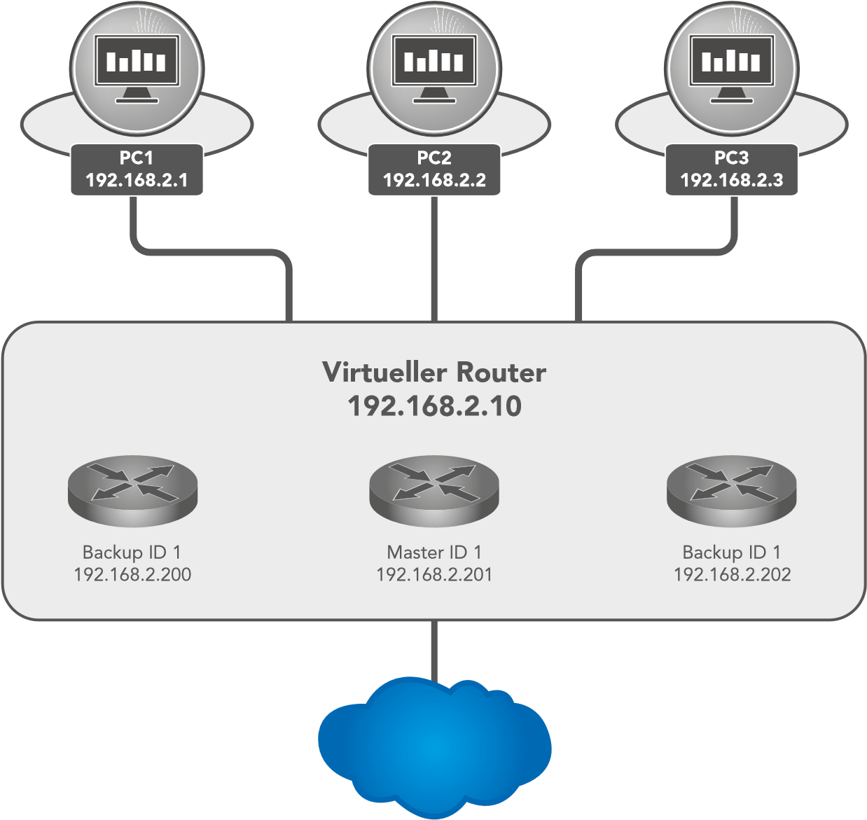
VRRP
In a network, all participants have a common gateway for communication with other networks. If this gateway fails, communication with other networks (and the Internet) is no longer possible.
For this reason, there is the Virtual Router Redundancy Protocol (VRRP). This makes it possible to operate several routers (gateways) in tandem, but only one is active (master) at any given time. The other routers serve as backup if the master fails. All routers together represent a virtual router. Within this virtual router, VRRP then regulates the communication, so that if the master fails, a backup router immediately becomes the new master and thus the new gateway for the network.
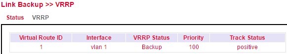
VRRP Status
Displays the status of the VRRP. Please refer to the description for details.
Parameter |
Description |
|---|---|
Virtual Route ID |
Displays the router group in which the router is located |
Interface |
Displays the LAN interface |
VRRP Status |
Displays the current status, master or backup |
Priority |
Displays the priority of the router |
Track Status |
Displays whether the connection check is successful |
VRRP Configuration

Parameter |
Description |
|---|---|
Enable |
Enables or disables the configuration |
Virtual Route ID |
Freely selectable, specifies the virtual router group. Must be identical for all routers within the group. |
Interface |
The LAN Interface |
Virtual IP |
The virtual router IP, must be identical for all routers within the same group. |
Priority |
0-254 the higher, the stronger. The highest value within the group automatically becomes the master. |
Advertisement Interval(s) |
Time to check within the group to find out who is the master. |
Preemption Mode |
If switched on, the router automatically checks whether the priority is higher than that of the current master. If it is, then it makes itself the master and the current master becomes the backup router. |
Track ID |
Previously created track for connection check |
VRRP Example:
First, set up a new SLA under Link Backup > SLA and then a track under Link Backup > Track. Then configure Router A via Link Backup > VRRP > VRRP as shown in Figure 1.

Figure 1 (Interface may differ depending on router model)
Now you can configure Router B as shown in Figure 2.
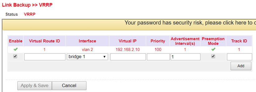
Figure 2 (Interface may differ depending on router model)
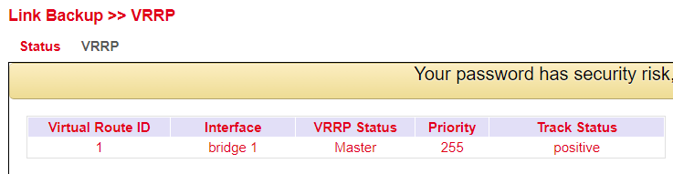
If you now go to the status page of VRRP (Link Backup > VRRP > Status) you should see the following on the routers:
Router A
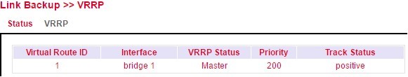
Router B
Interface Backup
Here you can create a backup of the interfaces of your router. If one interface fails, the other interface takes over the functions. To be accessed under Link Backup > Interface Backup.
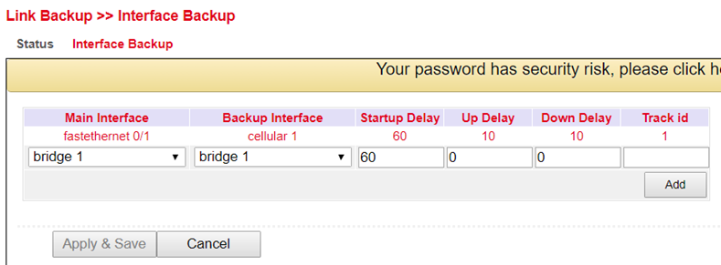
Interface Backup Configuration
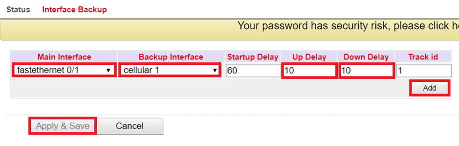
Under Link Backup > Interface Backup and Interface Backup you can define which interface should be the main interface and which should be the backup interface.
Parameter |
Description |
|---|---|
Main Interface |
The main interface is defined here. |
Backup Interface |
The backup interface is defined here. |
Startup Delay |
Delay in seconds at system startup. |
Up Delay |
Delay when switching from the backup interface to the main interface. |
Down Delay |
Delay when switching from the main interface to the backup interface. |
Track ID |
The track index, from the previously created track entry. |
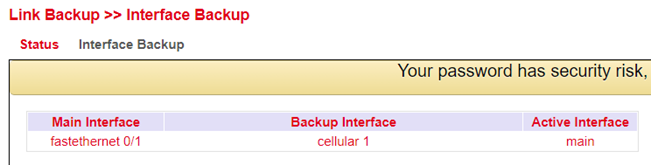
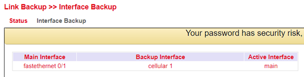
Interface Backup Status
On the status page you can see which interfaces have been defined as main and backup. You can also see which interface is currently active (Active Interface main).
Routing
Routing is a generic term for the transport route of data packets between different networks controlled by routers. On the Internet, data packets can take completely different routes, since there are no direct connections between computers on the Internet. The destination of the data is contained in the so-called header. The data packets are not reassembled correctly until they reach the recipient. Routing allows data traffic to be very flexible and fail-safe.
Static Routing
Static routing, as the name suggests, is based on a fixed default path between any two end systems. The default is made when a network is installed and is usually stored as a fixed routing table in the router. The end devices are each assigned to a router via which they can be reached and can reach other destinations. To be reached under Routing > Static Routing.
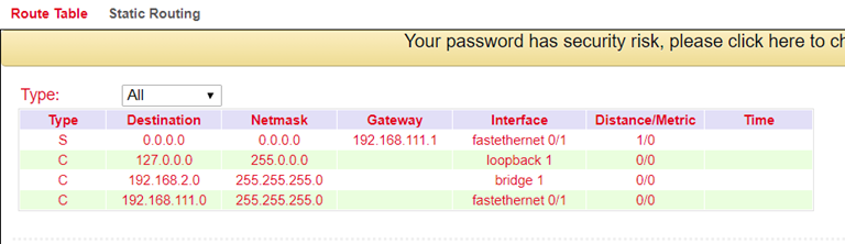
Route Table
The routing table can be found in the navigation under: Routing > Static Routing > Routing Table and Routing > Dynamic Routing > Routing Table
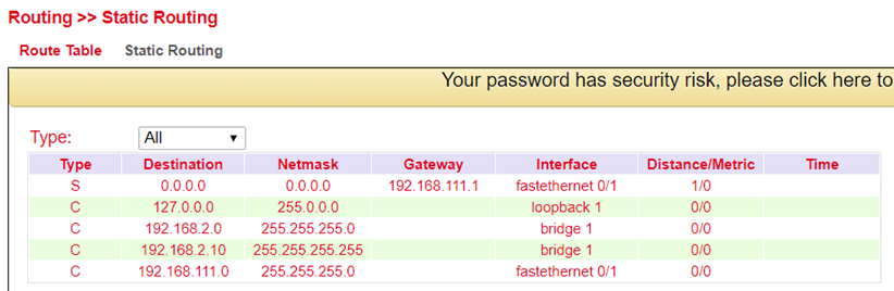
Parameter |
Description |
|---|---|
Type |
C = Connected / directly connected route, you are automatically added to a routing table when an interface is configured with an IP address S = Static route / manually entered route by the administrator R = RIP (Routing Information Protocol) / dynamic route added by RIP O = OSPF (Open Shortest Path First) / dynamic route added by OSPF |
Destination |
The destination is the target host, subnet address, network address, or default route. The destination for a default route is 0.0.0.0. |
Netmask |
The network mask is used with the destination to determine when a route is used. For example, a host route has a mask of 255.255.255.255, a default route has a mask of 0.0.0.0, and a subnet or network route has a mask between these two values. |
Gateway |
The gateway is the IP address of the next router to which a packet must be sent. |
Interface |
The interface is the network interface to be used to get to the next router. Cellular 1 = radio interface GSM Loopback 1 = internal loopback address (loopback) FastEthernet 0/1 = network port FastEthernet 0/1 on the router VLAN 1 = network ports which are assigned to VLAN 1. |
Distance/ Metric |
Distance/Metric is the priority of the route. If several routes lead to the same destination, the route with the lowest metric is considered the best route. |
Time |
Time |
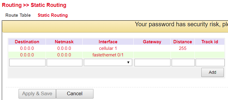
Static Routing
Static routes are set up in the navigation under Routing > Static Routing > Static Routing. Normally no static route has to be entered. The router enters the routes itself by making changes in the configuration.
Parameter |
Description |
|---|---|
Destination |
The destination is the destination host, subnet address, network address, or default route. The destination for a default route is 0.0.0.0. |
Netmask |
The network mask is used with the destination to determine when a route is used. For example, a host route has a mask of 255.255.255.255, a default route has a mask of 0.0.0.0, and a subnet or network route has a mask between these two values. |
Interface |
The interface is the network interface to be used to get to the next router. cellular 1 = radio interface GSM fastethernet 0/1 = network port FastEthernet 0/1 on the router VLAN 1 = network ports, which are assigned to VLAN 1. bridge 1 = at TK8X5-EXW and TK8X2 |
Gateway |
The gateway is the IP address of the next router to which a packet must be sent. |
Distance |
Distance/Metric is the priority of the route. If several routes lead to the same destination, the route with the lowest metric is considered the best route. |
Track id |
Track index or identification number |
Dynamic Routing
Dynamic routing is used to have routes controlled automatically by the routing protocol used. The advantage of dynamic routing over static routing is that the route selection is dynamic, i.e. it takes place during operation. Routes are learned and set automatically by the algorithm of the routing protocol.
Route Table
The routing table can be found in the navigation under:
Routing > Dynamic Routing > Routing Table
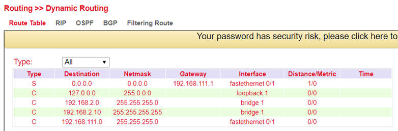
Parameter description see 3.5.1.1
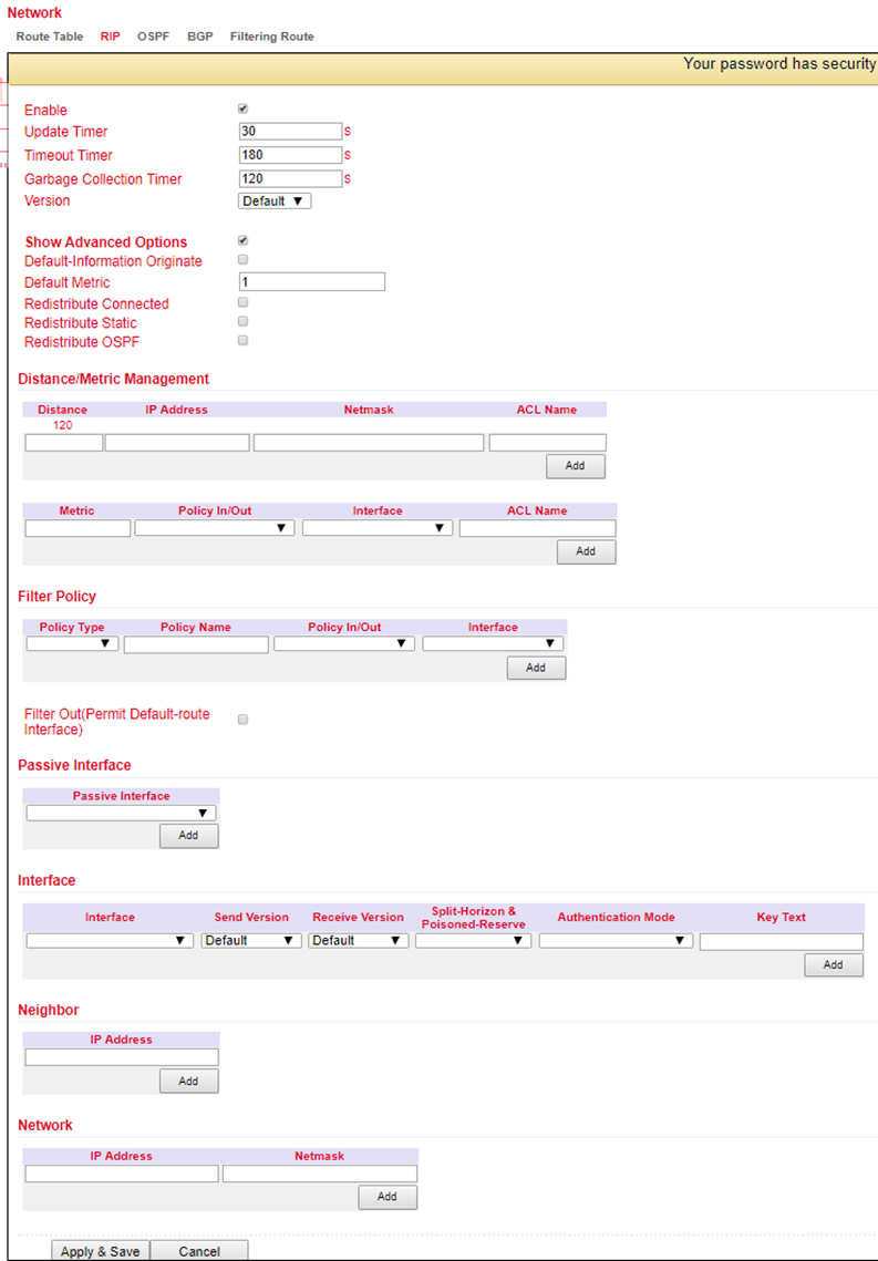
RIP
RIP (Routing Information Protocol) is a dynamic routing protocol that uses a distance vector algorithm. RIP learns dynamic routing addresses from other routers and stores them in its routing tables. The distance and costs to other networks are put into relation from the router’s point of view and the cheapest way to the destination network is also specified in the routing tables. Based on this information, the cheapest and shortest path to the destination network can be determined and taken. 15 hops is the maximum distance that a path to the destination network may be during RIP.
In the menu Routing > Dynamic Routing > RIP you can adjust the following settings:
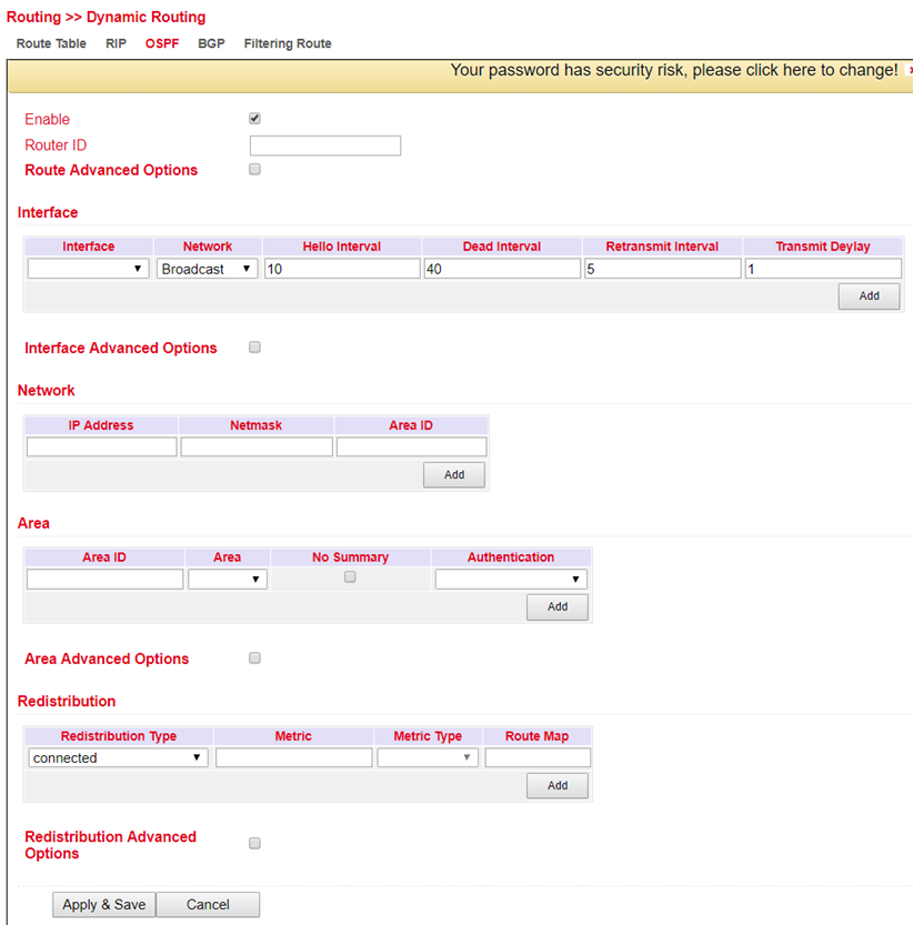
OSPF
OSPF (Open Shortest Path First) is a dynamic routing protocol that describes how routers propagate the availability of connection paths between data networks. It supports hierarchical network structures and, in contrast to RIP, several simultaneous connection paths of the same cost to a subnetwork. It is able to transmit the occurring data traffic over different connection paths. The OSPF protocol is particularly fast with respect to changes in the network topology and is characterized by economical use of bandwidth when creating new routing tables.
In the menu Routing > Dynamic Routing > OSPF you can adjust the following settings:
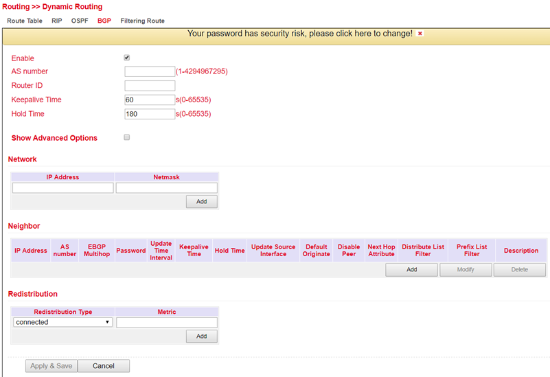
BGP
The Border Gateway Protocol (BGP) is the routing protocol used on the Internet and connects autonomous systems (AS) with each other. These autonomous systems are usually formed by Internet service providers. BGP is commonly referred to as Exterior Gateway Protocol (EGP) and Path Vector Protocol and uses both strategic and technical-metric criteria for routing decisions, although in practice business aspects are usually taken into account. Interior gateway protocols (IGP) such as OSPF are used within autonomous systems.
In the menu Routing > Dynamic Routing > BGP you can adjust the following settings for BGP:
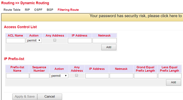
Filtering Route
In the menu Routing > Dynamic Routing > Filtering Route you can adjust the following settings:
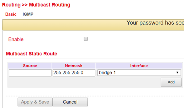
Multicast Routing
The Internet Group Management Protocol (IGMP) is based on the Internet Protocol (IP) and enables IPv4 multicasting (group communication) on the Internet. IP multicasting is the distribution of IP packets under one IP address to multiple stations simultaneously.
Basic
In the menu Routing > Multicast Routing > Basic you can adjust the following settings:
IGMP
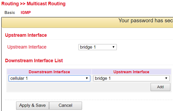
The Upstream Interface is used to select the interface over which the multicast is to be distributed.
With the Downstream Interface List the interfaces for the downstream and upstream interface are selected from the drop-down menu.
The interfaces may vary depending on the model.
Firewall
ACL
The ACL (Access Control List) is an access control list to control usage and administration. The ACL defines which computers or networks can access the router or networks behind the router. With the ACL, incoming and outgoing data packets are analyzed and managed according to the ACL ruleset.
ACL rules can be created on source and destination IP addresses, TCP and UDP port numbers, etc. to control access.
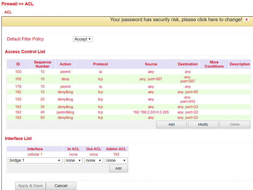
Here is an overview of the existing ACL rules. To create a new ACL you should click Add.
Standard ACL can allow or block any communication from a network or to a network, or prohibit all communication.
Extended ACL provides extended setting options for source and destination networks within an ACL. Protocols from different levels can be selected. This means that individual services such as Web (http), FTP, Telnet, etc. can be allowed or forbidden.
Parameter |
Description |
|---|---|
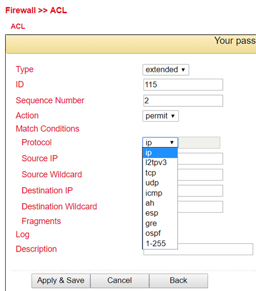
Type |
extended or standard |
ID |
ID 100 is preconfigured by default. Further IDs can be configured freely. |
Action |
Permit / Deny |
Protocol |
Protocols that are available |
Source IP |
Source IP address or network e.g. 192.168.2.0 |
Source Wildcard |
Source wildcard is the wildcard address of the subnet. E.g. for the subnet mask 255.255.255.0 the wildcard address is 0.0.0.255 |
Destination IP |
Destination IP address or network e.g. 172.16.0.0 |
Destination Wildcard |
Target wildcard is the wildcard address of the target subnet e.g. with subnet mask 255.255.0.0 the wildcard address is 0.0.255.255 |
Description |
Text Description field for the ACL |
NAT
Network Address Translation (NAT)
In computer networks, Network Address Translation (NAT) is the collective term for procedures that automatically replace address information in data packets with other information in order to connect different networks. For this reason, they are typically used on routers.
Use of Source NAT
It allows devices with private network addresses to connect to the Internet. Private IP addresses cannot usually be routed by the provider, so they must be translated into a public, routable IP address. The TK800 has implemented this function, which enables communication between different networks. In addition, a relevant security aspect is found in NAT, since a public IP address cannot be traced back to the associated private IP address. This function is configured in the TK800 router at the factory.
Use of Destination NAT
This is used to provide server services running on computers under a single IP address. It is often referred to as port mapping or port forwarding. This function must be explicitly set up on the TK800.
Use of 1:1-NAT
A special form of destination NAT is 1:1 NAT. It is used, for example, when a central location wants to access different sites via VPN, which are all configured with the same IP network addresses. This is frequently encountered in machine networks.
Configuration
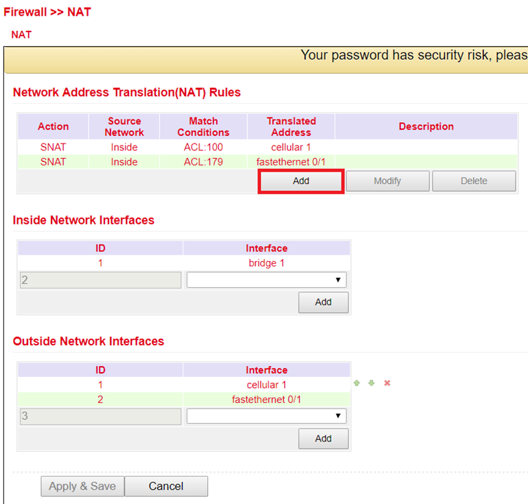
to configure NAT, go to the Firewall menu item and select NAT
here you can find a list of all existing NAT rules and the definition of the Inside-(LAN-) and Outside-(WAN-) interfaces
(Note: For some use cases it is necessary to create and use an ACL (Access Control List))
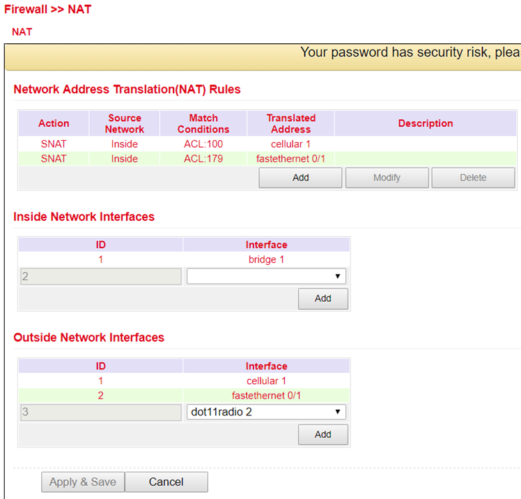
by clicking Add a new NAT rule can be configured in the following menu (Fig. 2)
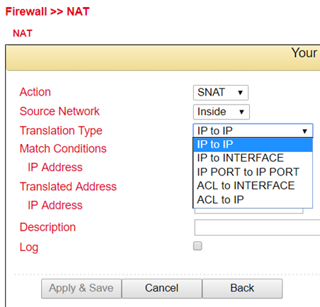
Action |
|
|---|---|
SNAT |
Rewrite IP address of the computer that establishes the connection |
DNAT |
Rewrite IP address of the addressed computer |
1:1NAT |
Translate IP address one-to-one |
Source Network |
|
Inside |
Packets originate from an internal interface (LAN) |
Outside |
Packets originate from an external interface (WAN) |
Translation Type |
|
IP to IP |
Translate one IP address to another |
IP to Interface |
Translate an IP address to the IP address of a single interface |
IP Port to IP Port |
Translate one combination of IP address and port to another |
ACL to Interface |
Translate an IP address according to ACL rule into an IP address of a single interface |
ACL to IP |
Translate an IP address to another IP address according to ACL rule |
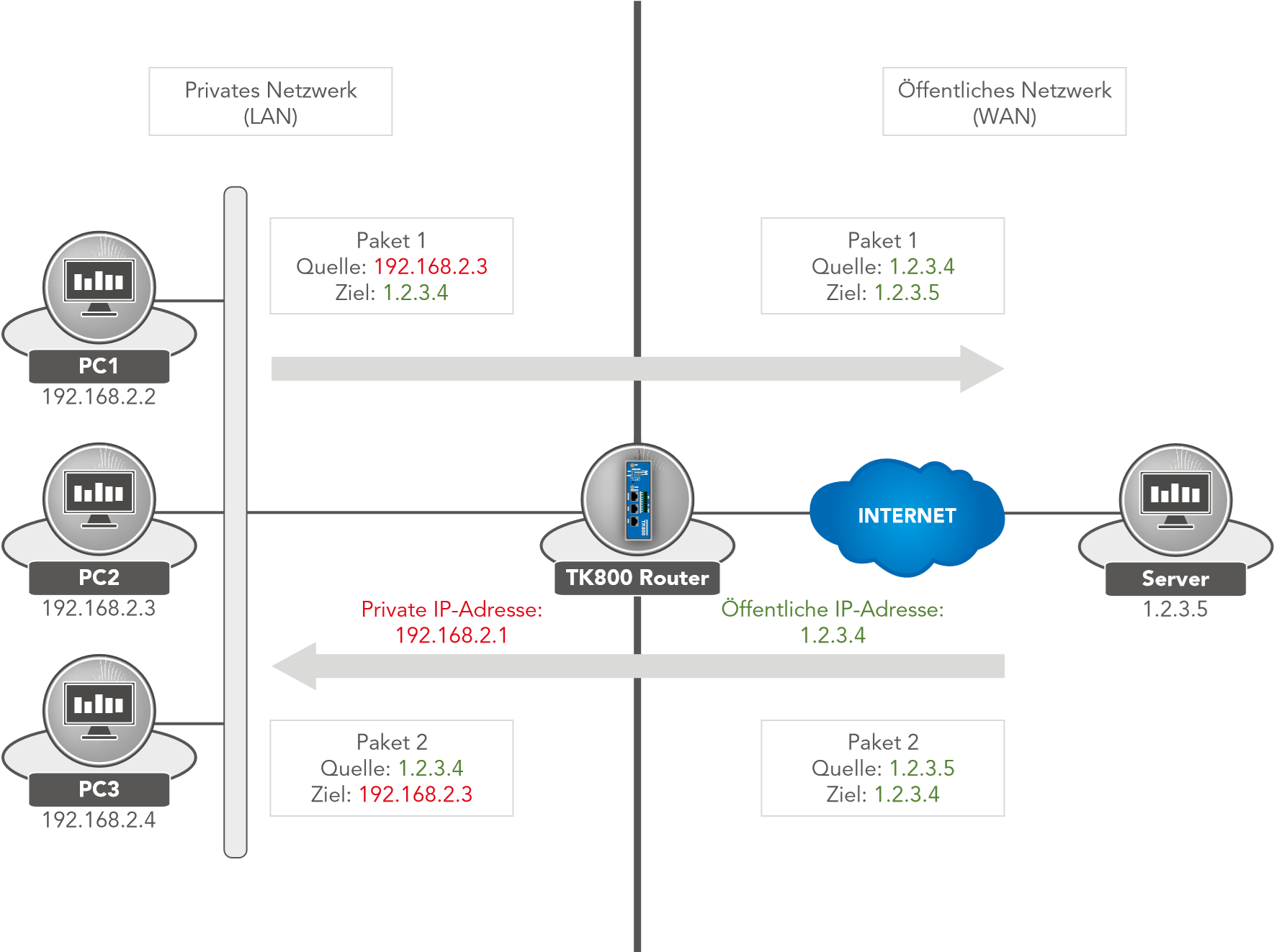
Examples Case 1: SNAT (TC router as Internet gateway)
The TK800 works as an Internet gateway for connected devices with private IP addresses. It translates private IP addresses from the LAN into a public, routable Internet address.
(Note: This is the factory setting of all Welotec routers).
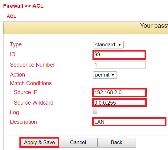
Configure the ACL rule. To do this, go to the Firewall menu and select the ACL subitem.
Now assign an ID for the rule and enter the IP address and the corresponding Wildcard mask.
(Note: The wildcard mask is the inverted netmask and is used by routers to edit ACLs (Access Control Lists)).
Now configure the SNAT rule.
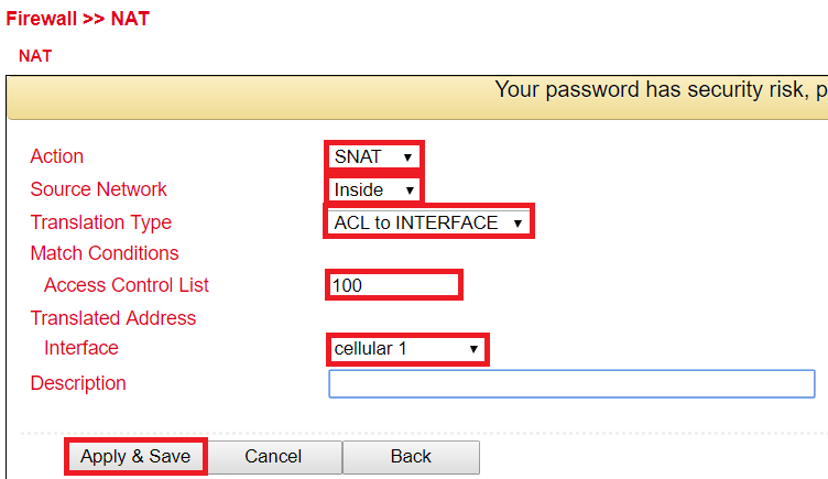
Now define the inside and outside interface.
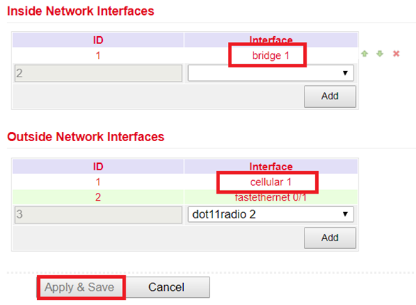
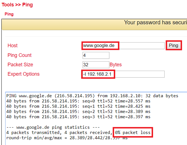
Test the access via the tool ping. This can be done directly from the router. To do this, go to the Tools menu to the Ping subitem and enter the values according to the example.
(Note: Use the Expert option –I 192.168.2.1 (capital i) so that access is from the inside (LAN) interface of the TK800 router).
Case 2: DNAT (Portmapping / Port Forwarding)
Access to connected devices via the Internet
Usually, users want to access devices connected to the Welotec Router via the Internet. Since these devices (e.g. webcam, control of a PLC, etc.) do not have their own mobile or Internet access, the Welotec Router must forward the requests from the Internet to the devices. This is done using the so-called port forwarding / port mapping function.
Private network (LAN) |
Public network (WAN) |
|
|---|---|---|
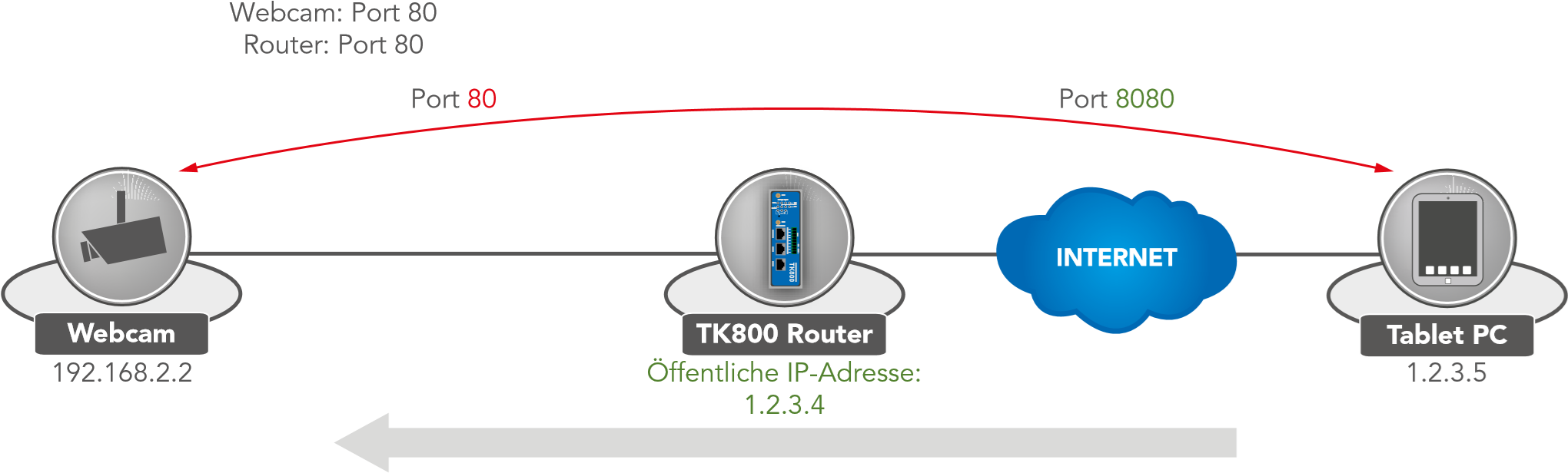
Packet Source: 1.2.3.4.8080 Destination: 192.168.2.2.80 |
Package Source: 1.2.3.5.8080 Destination: 1.2.3.4.8080 |
|
|---|---|---|
Requirements
Public IP address in the mobile network (or also for wired Internet connections).
(Note: Many mobile operators offer tariffs for business customers to access mobile devices, e.g. T-Mobile IP VPN or Vodafone CDA. Furthermore, there are providers who provide you with a public IP address via a conventional mobile phone card).
Router Firmware 1.0.0.r9919 or higher
Port Mapping Notes
The following information must be available for port mapping to be set up:
IP address of the device that is to be accessed
Port to be redirected (e.g. http/80 from the device that is to be accessed).
Example Welotec Router
LAN IP address: |
192.168.2.1 |
|---|---|
Subnet mask: Webcam |
255.255.255.0 |
LAN IP address: |
192.168.2.2 |
Subnet mask: |
255.255.255.0 |
Standard Gateway: |
192.168.2.1 |
The webcam has an interface that can be accessed via http://192.168.2.2.
(Note: http protocol uses TCP port 80)
For a working port mapping it is helpful to check the settings of the connected devices in advance. The following checklist is helpful (according to the example above):
Does the camera have the IP address 192.168.2.2?
Does it respond to “ping 192.168.2.2”?
Is the web interface of the camera accessible via http://192.168.2.2?
Is the Welotec router entered as the default gateway for the camera (192.168.2.1)?
If these conditions are met, the port mapping can be set up according to the following instructions.
Configuration
Go to the menu item Firewall and select the sub-item NAT.
Now add a new NAT rule with Add
Enter the data as shown in the example
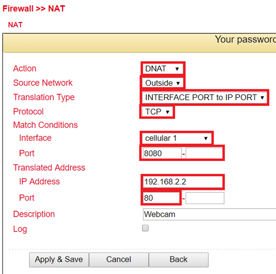
By calling the router IP with the corresponding port, the connected device can be reached

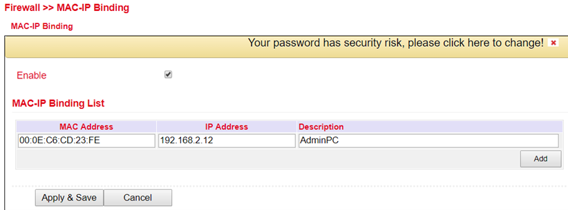
MAC-IP Binding
MAC-IP Binding can be found in the navigation tree under Firewall > MAC-IP Binding .
MAC-IP Binding can be used to ensure that a device (PC, server, etc.) can only access the router if the MAC and IP addresses entered here match.
Parameter |
Description |
|---|---|
MAC-Address |
Enter the MAC address of the device here in the format XX : XX : XX : XX: XX : XX. A typical MAC address looks like this: 00:FF:4E:85:F1:B5 |
IP-Address |
Enter the IP address which the device should get, e.g. 192.168.2.150 |
Description |
Text description field |
VPN
Virtual Private Network, or VPN for short. The VPN is used to link participants in the existing communications network to another network. For example, an employee’s computer can gain access to the company network from home, just as if he were sitting right in the middle of it.
IPsec
IPsec (short for Internet Protocol Security) is a protocol suite designed to enable secure communications over potentially insecure IP networks such as the Internet. The goal is to provide encryption-based security at the network level. IPsec provides this capability through connectionless integrity and access control and authentication of data. In addition, IPsec ensures confidentiality as well as authenticity of the packet sequence through encryption.
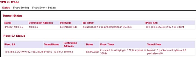
Status
If the IPsec tunnel(s) have been successfully established, you will see the following in the status overview.
IPsec Setting
Under VPN > IPsec > IPsec Setting, existing settings can be adjusted or a new IPsec tunnel can be created. When creating a new IPsec tunnel, an IKE policy and an IPsec policy must first be created.
Afterwards, this setting must first be confirmed with Apply & Save. Then the actual IPsec tunnel can be created via Add.
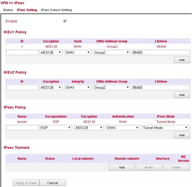
IKEv1 Policy:
Parameter |
Description |
|---|---|
ID |
Integer, can be freely selected. Used to identify the policy in the tunnel configuration |
Encryption |
Encryption method |
Hash |
Hash algorithm |
Diffie-Hellman Group |
DH Group for key exchange |
Lifetime |
Period of validity of the IKE before it is renegotiated |
IKEv2 Policy:
Parameter |
Description |
|---|---|
ID |
Integer, can be freely selected. Used to identify the policy in the tunnel configuration |
Encryption |
Encryption method |
integrity |
Hash algorithm |
Diffie-Hellman Group |
DH Group for key exchange |
Lifetime |
Period of validity of the IKE before it is renegotiated |
IPsec Policy:
Parameter |
Description |
|---|---|
Name |
Freely selectable name of the IPsec policy. Used to identify the policy in the tunnel configuration |
Encapsulation |
ESP or AH |
Encryption |
Encryption method |
Authentication |
Hash algortihm |
IPsec Mode |
Tunnel or Transport Mode |
IPsec Tunnel
Via VPN > IPsec > IPsec Setting you can create a new IPsec tunnel (IKEv1 and IKEv2) under IPsec Tunnels with Add. The prerequisite is that an IKEv1 or IKEv2 policy and an IPsec policy have been created beforehand.
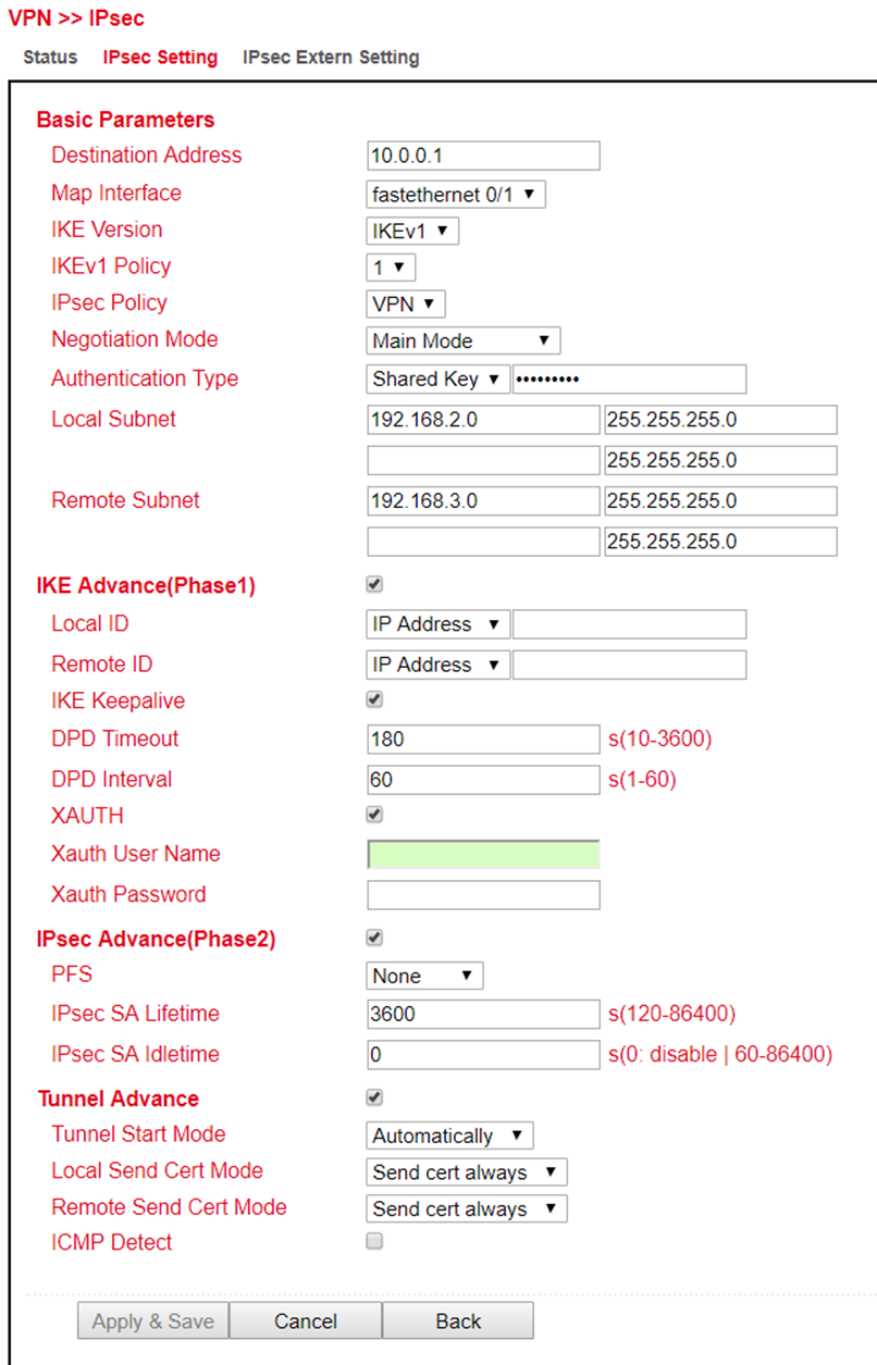
Basic Parameters:
Parameter |
Description |
|---|---|
Destination Address |
IP address of the tunnel remote station |
Map Interface |
Interface of the router through which the connection is to be established |
IKE Version |
IKEv1 or IKEv2 |
IKEv1 Policy |
The ID number of the previously created IKEv1 policy. |
IPsec Policy |
The name of the previously created IPsec policy |
Negotiation Mode |
Main Mode or Agressive Mode |
Authentication Type |
Shared Key or Certificate |
Local Subnet |
The router subnet |
Remote Subnet |
The remote station subnet |
IKE Advance(Phase1):
Parameter |
Description |
|---|---|
Local ID |
IP Address, FQDN or User FQDN |
Remote ID |
IP Address, FQDN or User FQDN |
IKE Keepalive |
Switches IKE Keepalive on or off |
DPD Timeout |
Timeout for a DPD packet |
DPD Interval |
Interval of DPD packets |
XAUTH |
Switches XAUTH on or off |
Xauth User Name |
XAUTH User Name |
Xauth Password |
XAUTH Password |
IPsec Advance(Phase2):
Parameter |
Description |
|---|---|
PFS |
Perfect Forward Secrecy Group |
IPsec SA Lifetime |
Validity period of SA before it is recreated |
IPsec SA Idletime |
SAs associated with inactive peers can be deleted before the global lifetime expires. |
Tunnel Advance: |
Parameter |
Description |
|---|---|
Tunnel Start Mode |
Selection of the start mode for the tunnel. Automatic is the default. |
Local Send Cert Mode |
Specifies when the certificate should be sent |
Remote Send Cert Mode |
Specifies when the certificate should be sent |
ICMP Detect |
Switches the ICMP watchdog on or off |
ICMP Detection Server |
To test the IPsec tunnel connection, a server must be specified here that can only be reached through the tunnel |
ICMP Detection Local IP |
The router interface IP of the local subnet is specified here |
ICMP Detection Interval |
Interval at which the ICMP packet is sent |
ICMP Detection Timeout |
Time after which the ICMP packet is discarded |
ICMP Detection Max Retries |
Maximum attempts after a failed ICMP ping |
IPsec Extern Setting
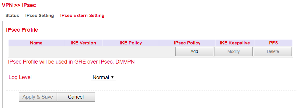
IPsec profiles are used with GRE over IPsec. The profile is created via the ADD button.
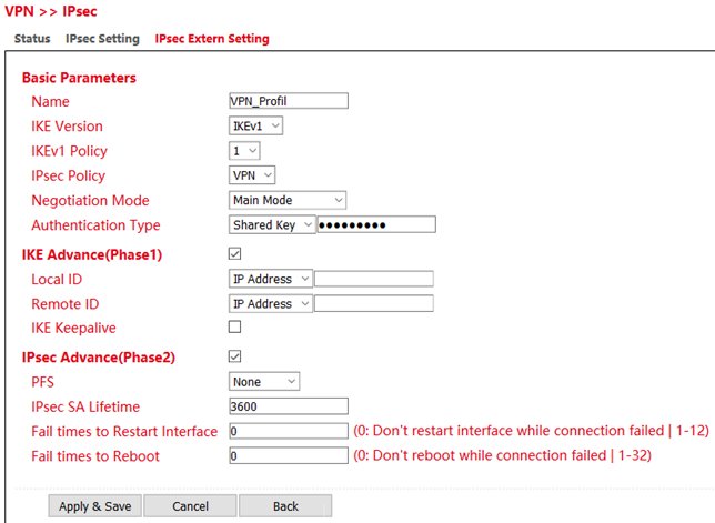
Parameter |
Description |
|---|---|
Name |
Unique name for the external settings of the IPsec |
IKE Version |
IKEv1 or IKEv2 |
IKEv1 Policy |
The ID number of the previously created IKEv1 policy |
IPsec Policy |
The name of the previously created IPsec policy |
Negotiation Mode |
Main Mode or Agressive Mode |
Authentication Type |
Shared Key or Certificate |
IKE Advance (Phase1)
Parameter |
Description |
|---|---|
Local ID |
IP Address, FQDN or User FQDN |
Remote ID |
IP Address, FQDN or User FQDN |
IKE Keepalive |
Switches IKE Keepalive on or off |
DPD Timeout |
Timeout for a DPD packet |
DPD Interval |
Interval of DPD packets |
***\ |
|
IPsec Advance (Phase2)*** |
Parameter |
Description |
|---|---|
PFS |
Perfect Forward Secrecy Group |
IPsec SA Lifetime |
Validity period of the SA before it is recreated |
Fail times to Restart Interface |
Number of failed connection attempts after which the IPsec tunnel should be restarted |
Fail times to Reboot |
Number of failed connection attempts after which the router should be restarted |
GRE
The GRE (Generic Routing Encapsulation) protocol is used to encapsulate other protocols and transport them over tunnels.
GRE is used when dynamic routing is to be implemented via the IPSec tunnel.
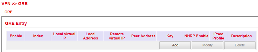
Overview page. A new GRE entry is added with Add.
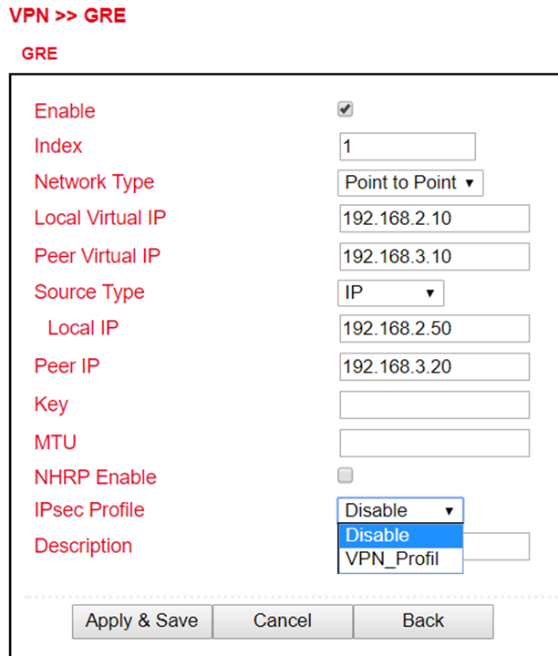
Under IPsec Profile the profile created under VPN > IPsec > IPsec External Setting is now in the selection list.
L2TP
L2TP (Layer 2 Tunneling Protocol) combines PPTP (Point to Point Tunneling Protocol) and L2F (Layer 2 Forwarding). L2TP only supports user authentication, but no encryption. Therefore, L2TP is used in conjunction with an IPSec tunnel to guarantee encryption. L2TP is often used to connect single computers (keyword: road warrior) to the network.
L2TP Status
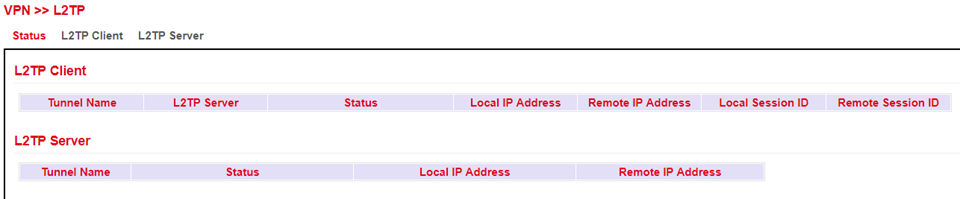
L2TP Client
Under VPN > L2TP > L2TP Client the corresponding client for the tunnel is created. The respective entries must be added with the Add button and are only completely saved when the Apply & Save button is clicked.
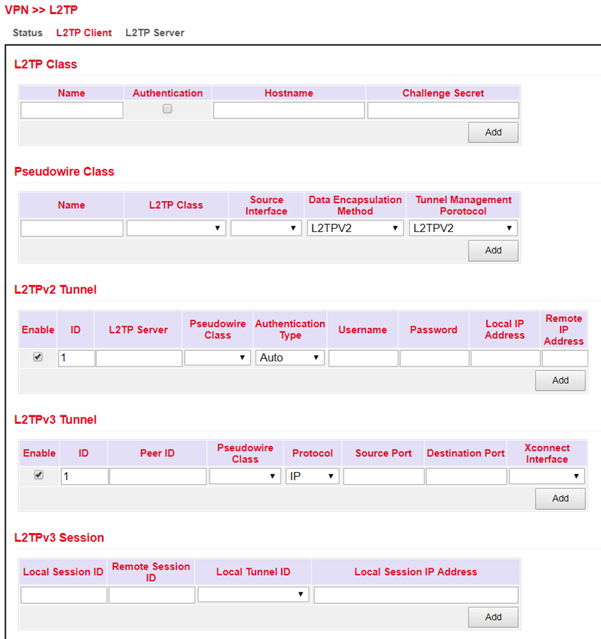
L2TP Server
Here you can create a corresponding L2TP server.
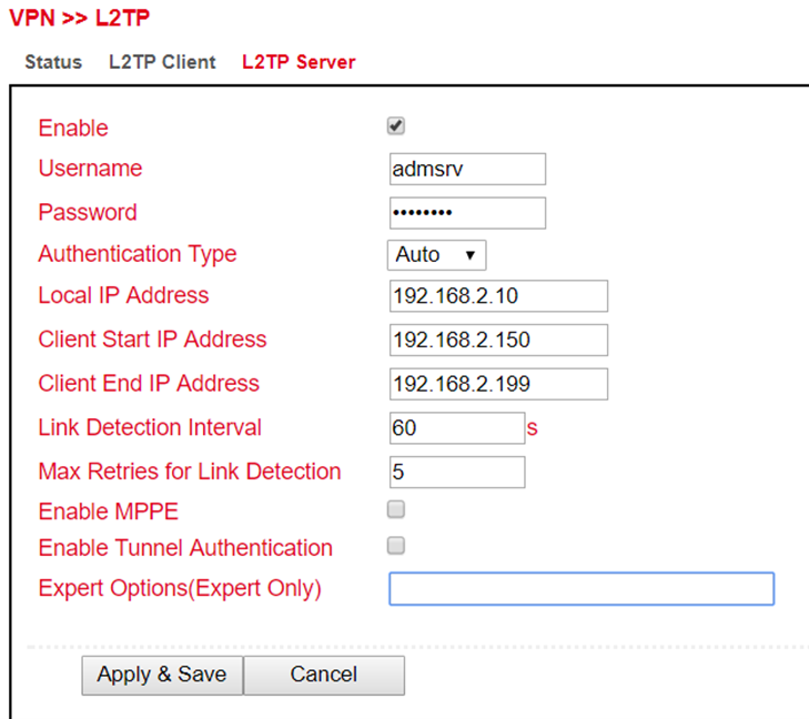
OpenVPN
OpenVPN is a free software for setting up a Virtual Private Network (VPN) over an encrypted TLS connection. The OpenSSL library is used for encryption. OpenVPN uses either UDP or TCP for transport.
OpenVPN Status
Status overview of the OpenVPN that has been configured.
Client Status:
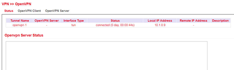
Server Status:
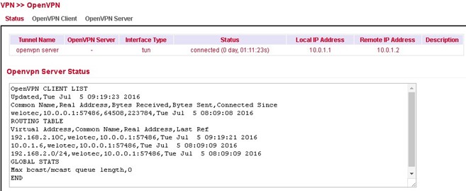
OpenVPN Client
A new OpenVPN tunnel can be added under VPN > OpenVPN > OpenVPN Client. The router has to be configured as a client.
A new configuration can be created via the “Add “ button.
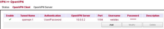
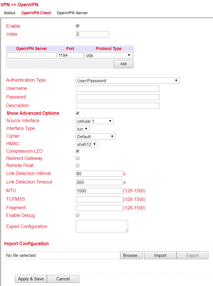
Depending on the selected authentication, different inputs are possible. This example deals with username / password.
Parameter |
Description |
|---|---|
Enable |
Switches the OpenVPN client on or off |
Index |
Freely selectable, for identification purposes only |
OpenVPN Server |
The IP address or the FQDN of the OpenVPN server |
Authentication Type |
Authentication method (recommended x509-cert) |
Username |
Username |
Password |
Password |
Description |
Brief description of the client |
Show Advanced Options:
Parameter |
Description |
|---|---|
Source Interface |
The interface over which the OpenVPN tunnel is to be established |
Interface Type |
tun or tap (recommended tun) |
Cipher |
Encryption method |
HMAC |
Signs all packets involved in the TLS handshake. Sha1 is default |
Compression LZO |
Enable or disable compression of data |
Redirect-Gateway |
If redirect gateway is enabled, the traffic is routed through the tunnel |
Remote Float |
If Remote Float is enabled, the client will also accept packets that match the authentication but do not originate from the server address. This option is useful if the server has a dynamic IP address |
Link Detection Interval |
Interval at which the tunnel connection is checked |
Link Detection Timeout |
Timeout for a tunnel connection check packet |
MTU |
Maximum packet size |
TCPMSS |
Specifies the maximum size for TCP packets |
Fragment |
Maximum packet size for UDP packets |
Enable Debug |
Switches debug mode on or off |
Expert Configuration |
OpenVPN tunnel options that are not available via the web interface can be entered here directly |
The client always needs the CA certificate of the server, otherwise it cannot be authenticated.
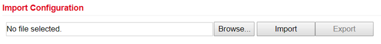
This can be used to import an already existing OpenVPN configuration or to export the current configuration. The OpenVPN configuration can be exported from the OpenVPN server. This then has the file extension .ovpn.
Please make sure that the OVPN file does not contain any spaces. Spaces are interpreted differently by the router.
OpenVPN Server
Via VPN > OpenVPN > OpenVPN Server you configure the router as OpenVPN. The prerequisite for this is that the router has a public IP address.
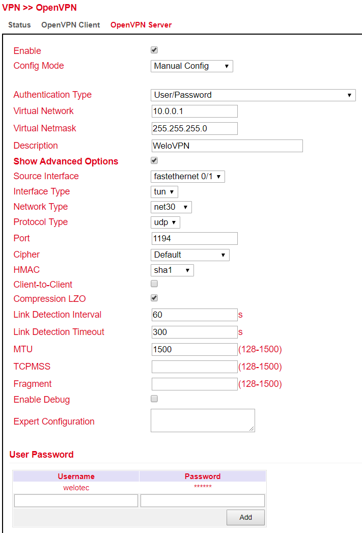
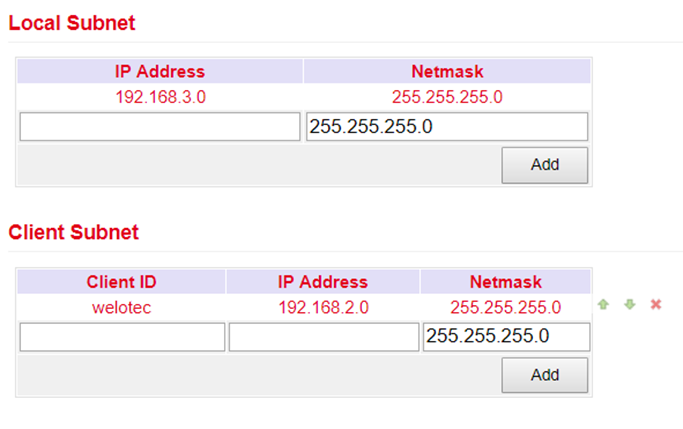
Depending on the selected authentication, different entries are possible. This example deals with username / password.
Parameter |
Description |
|---|---|
Enable |
Switches the OpenVPN server on or off |
Config Mode |
Here you can choose between the manual configuration and the import of a finished configuration |
Authentication Type |
Authentication method |
Virtual Network |
The virtual network for the OpenVPN Tunnel |
Virtual Netmask |
The netmask for the virtual network of the OpenVPN tunnel |
Description |
Brief description of the server |
Advanced Options:
Parameter |
Description |
|---|---|
Source Interface |
The interface over which the OpenVPN tunnel is to be established |
Interface Type |
tun or tap (recommended tun) |
Network Type |
Connection type (recommended net30) |
Protocol Type |
UDP or TCP |
Port |
Port on which the OpenVPN server will run |
Cipher |
Encryption method |
HMAC |
Message Authentication Code(MAC) whose construction is based on a cryptographic hash function |
Client-to-Client |
Enable or disable client-to-client connection |
Compression LZO |
Enable or disable compression of data |
Link Detection Interval |
Interval at which the tunnel connection is checked |
Link Detection Timeout |
Timeout for a tunnel connection check packet |
MTU |
Maximum packet size |
TCPMSS |
Sets the maximum size for TCP packets |
Fragment |
Maximum packet size for UDP packets |
Enable Debug |
Switches the debug mode on or off |
Expert Configuration |
OpenVPN tunnel options that are not available via the web interface can be directly entered here. |
User Password:
Clients can be added here, which can then log in with the user name and password.
Local Subnet:
Here the local subnets of the router are entered, which will be accessible for the clients.
Client Subnet:
The client subnets that are to be accessible from the server side are entered here. The Client ID is the username of the client for the authentication method Username/Password and the Common Name for certificates.
The OpenVPN server always requires a CA certificate, as well as a public key and a private key. These are uploaded via VPN > Certificate Management. If these certificates are not available, the server will not start!
Certificate Management
The certificates for an IPSec tunnel or an OpenVPN tunnel are stored in Certificate Management, provided that they are not secured via a Pre Shared Key (PSK).
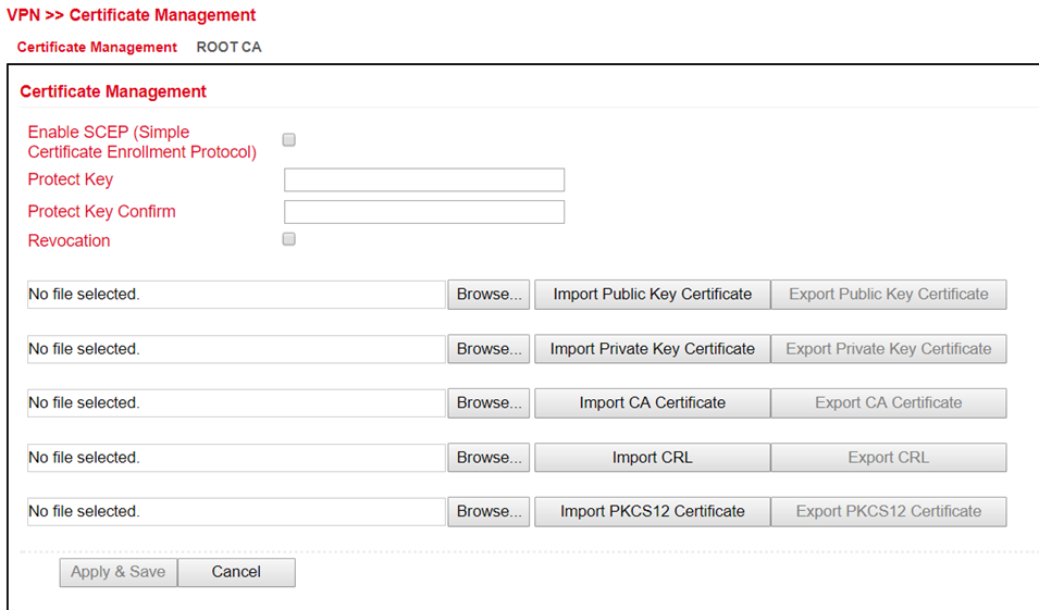
To upload a certificate, you have to click on “Browse”, select the locally stored certificate and then click on “Import…”.
The “Export Function” can be used to check whether the certificates have been uploaded properly.
If the files have a size of 0 bytes, try to upload the certificates with another browser or PC.
If a PKCS12 certificate set has been imported and is password protected, the password must still be entered under Protect Key and Protect Key Confirm after the import.
Then click on “Apply & Save” at the bottom to save the imported certificates in the configuration.
Parameter |
Description |
|---|---|
Enable SCEP |
SCEP (Simple Certificate Enrollment Protocol) is used to roll out secured certificates to network devices and users. Check the box to enable this feature. |
Protect Key |
If the certificate is password protected, then the password for the certificate must be entered in this field, otherwise it cannot be uploaded correctly. |
Protect Key Confirm |
Enter the certificate password again to confirm the correctness of the entered password. |
Revocation |
Enabling this function enables the creation of a revocation list for invalid certificates |
Import Public Key Certificate |
Public Key Certificate is the certificate of the public key |
Import Private Key Certivicate |
Private Key Certificate is the certificate of the private key. |
Import CA Certificate |
Certificate Authority (CA) is the certificate of the certification authority. |
Import CRL |
Certificate Revocation List is the certificate revocation list. |
Import PKCS12 Certificate |
PKCS12 Certificate |
APP
Python scripts can be uploaded under the menu item Administration > APP. The Python scripts can be executed and edited via the Command Line Interface (CLI).
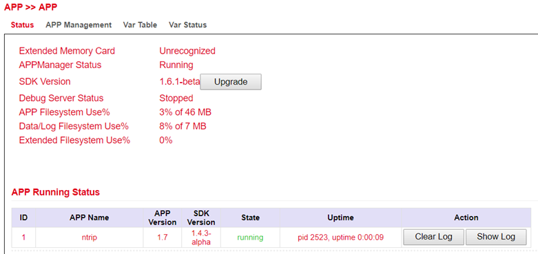
Status
Under the menu item APP > APP and Status you can see which Python SDK version is installed and which APP is running under Python. These APPs are then available to the Python scripts. You can also upgrade your Python SDK version via the upgrade button.
APP Management
To use the client IDE, it is necessary to enable the Enable IDE Debug function on the TK800. In addition, we recommend also enabling the APP Manager at this point. The App Manager gives you the possibility to install APPs under Python and to manage the existing apps in the Router-WebUI.
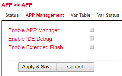
To do this, please enable the Enable APP Manager and Enable IDE Debug functions. Then click Apply & Save.
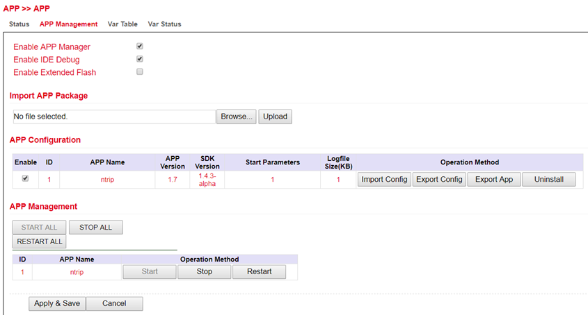
Upload application
Once you have created your application, you can import it to other TK800 routers.
To do this, you can select “APP -> APP -> APP-Management” and click “Browse” at Import APP Package.
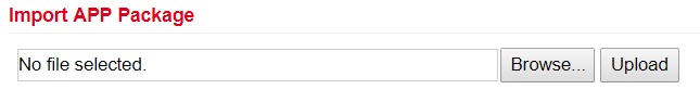
Select your .tar file and click Upload.
After you confirm the upload with “OK”, the application will be uploaded to the system.
After that you can upload your configuration if needed and enable the application by clicking “Enable”.
Var Table
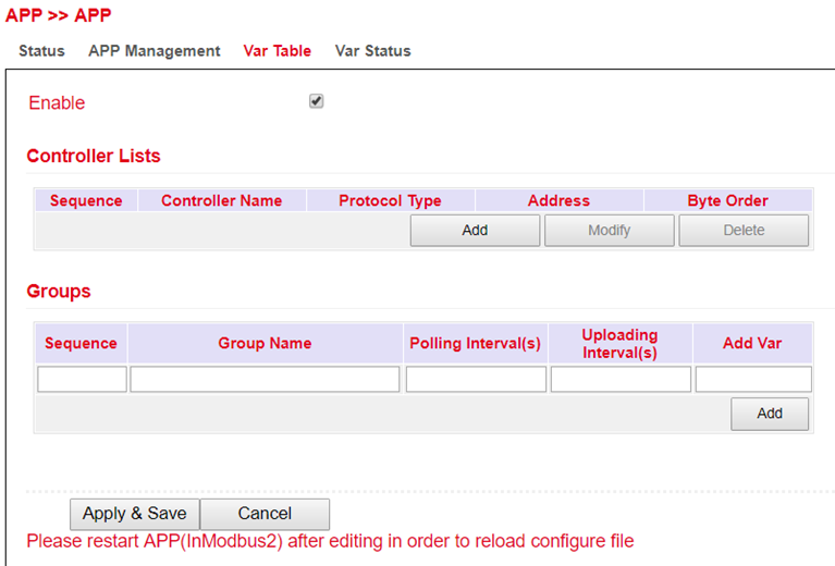
In this area you have the possibility to access Modbus with APPs. At the moment we do not support this function.
Var Status
If you use your own APPs for the access to Modbus, you have the possibility to display the status here. At the moment we do not support this function.
Industrial
The Industrial functions are available on all models of the TK800 series with EX in the name. Example: TK8X2L-EX0.
The following functions are available:
Digital input
Relay output
RS-232 interface
RS-485 interface
DTU
DTU stands for Data Terminal Unit and is used to connect devices with serial interface (RS-232 and RS-485). The configuration of the DTU properties always consists of two parts.
Under the item Serial Port the properties of the interface can be defined. Here you can find the parameters for the RS-232 and for the RS-485 interface.
Under the item DTU 1 (RS-232) and the item DTU 2 (RS-485) the protocols and the parameters for the protocols can be set.
Serial Port
At this point the serial ports 1 (RS232) and 2 (RS485) can be configured.
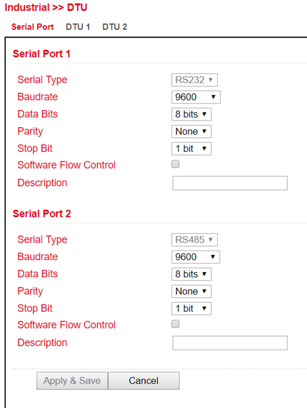
DTU 1 / DTU 2
Transparent
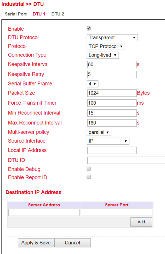
TCP server selection at DTU Protocol
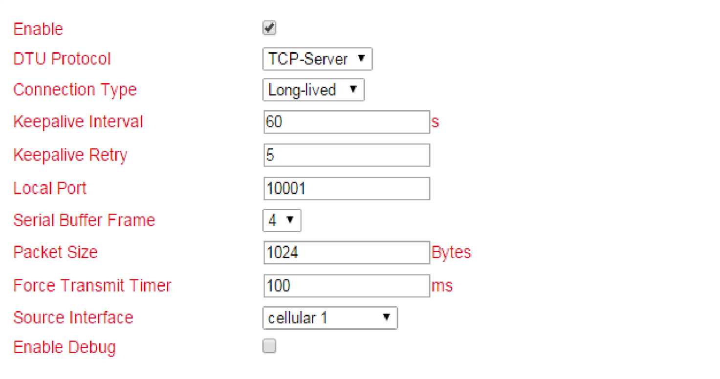
RFC2217 selection at DTU Protocol

IEC60870-5-101/104 selection at DTU Protocol
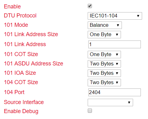
Select Modbus-Net-Bridge at DTU Protocol
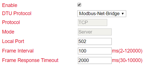
Selection DC Protocol at DTU Protocol
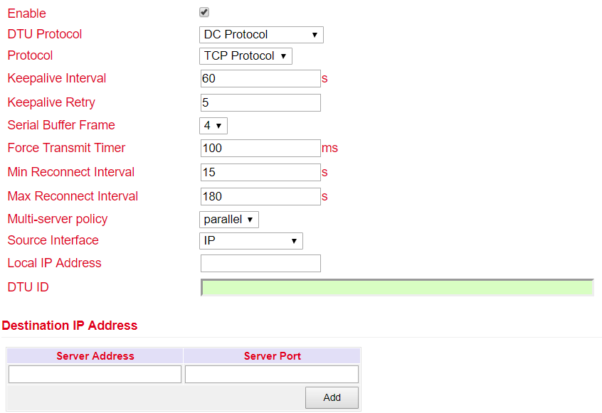
IO
Under Industrial > IO you can configure whether the digital input is to be used for switching the VPN connections. The relay is always ON by default.
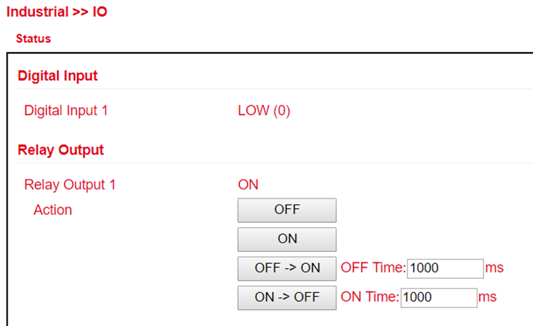
Digital Input:
Displays the status of the digital input.
Relay Output:
Parameter |
Description |
|---|---|
Relay Output 1 |
Relay output status |
Action |
Switch on, switch off or define a cycle |
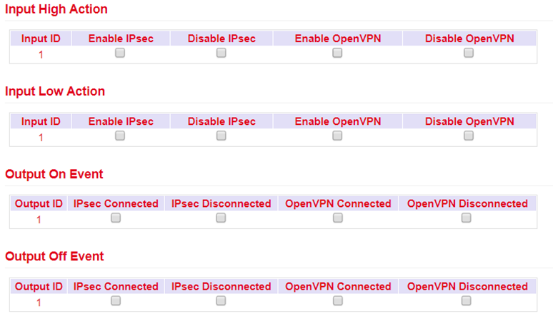
Input High/Low Action: Description
Default relay settings on or off. This can be used to switch the status of the relay output on or off or to define a corresponding cycle.
Here, an OpenVPN or IPsec tunnel can be started or stopped via the digital input.
Output On/Off Event:
Here the relay output can be used to start or stop IPsec and OpenVPN.
Modbus
Communication protocol based on a master / slave or client / server architecture. Modbus/TCP is very similar to RTU, but TCP/IP packets are used to transmit the data. TCP port 502 is reserved for Modbus/TCP.
Via Industrial > Modbus > Modbus Tcp you can switch the corresponding settings on or off.
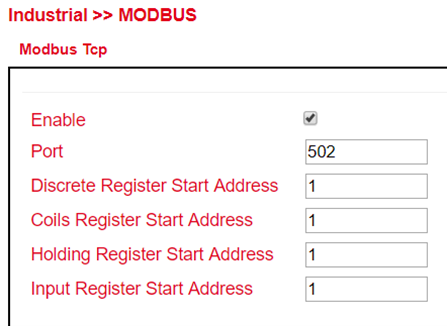
Tools
Useful tools that can be used for pinging, tracing, etc.
Ping
At this point in the router software, a ping can be sent to check connections, for example.
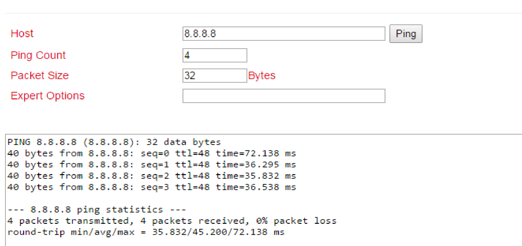
Parameter |
Description |
|---|---|
Host |
Enter the address to be pinged |
Ping Count |
Number of pings executed. Entry from 1 to 50 possible. Default is 4 |
Packet Size |
Size of the packet to be sent. Default is 32 bytes |
Expert Options |
Expert Options |
Traceroute
Traceroute (tracert) determines via which routers and Internet nodes IP data packets reach the queried computer.
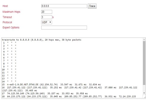
Parameter |
Description |
|---|---|
Host |
Enter the destination host to be detected |
Maximum Hops |
Number of executed hops. Input from 2 to 40 possible. Default is 20 |
Timeout |
Input of the timeout in seconds. Value can be between 2 and 10s. |
Protocol |
Optionally either ICMP or UDP. Default is UDP |
Expert Options |
Expert Options |
Tcpdump
Well-known and widely used packet sniffer. Allows TCP packets to be sniffed.
Via Tools > Tcpdump you can access this sniffer.
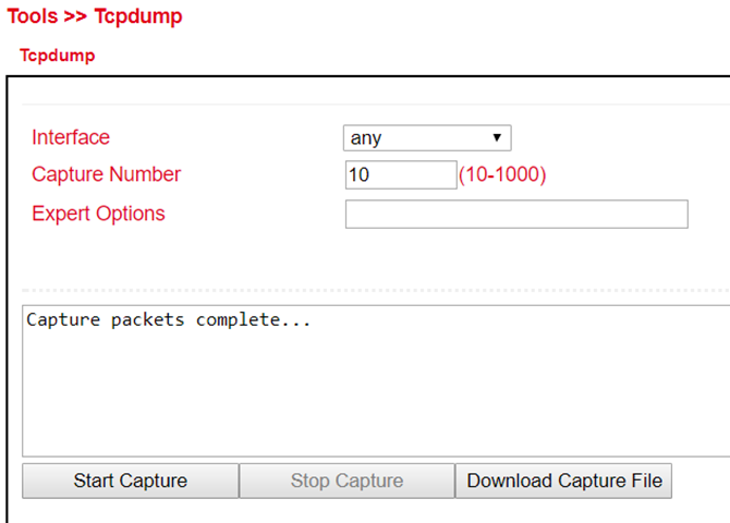
Parameter |
Description |
|---|---|
Interface |
Selection of the interface to be captured |
Capture Number |
Number of captures. Default is 10 |
Expert Options |
Expert Options |
Start Capture (Button) |
Starts capturing the data packets |
Stop Capture (Button) |
Stops capturing the data packets |
Download Capture File (Button) |
Downloads the capture as tcpdump.pcap file. Readable e.g. with Wireshark |
Link Speed Test
Determine the connection speed by uploading and downloading files.
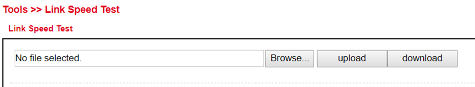
Via the Browse button you can upload a corresponding file from the computer. The file should be between 10 and 2000MB in size. After selecting the file, click the Upload button. The result will be displayed.
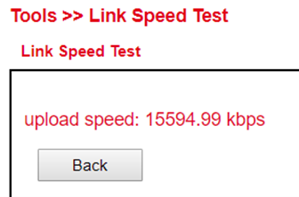
The download button downloads a 130MB file (test.bin) which shows the download speed during the download.
Wizards
These are wizards designed to facilitate the creation of the following processes.
New LAN
If you want to set up a new LAN interface, you can use the wizard under Wizards > New LAN. This will then create all the necessary data in the background.
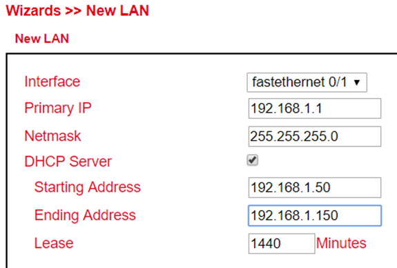
Parameter |
Description |
|---|---|
Interface |
The available interfaces of the router |
Primary IP |
The IP address to be assigned to the selected interface |
Netmask |
The netmask that the selected interface will receive |
DHCP Server |
Switches the DHCP server for this interface on or off |
Starting Address |
If the DHCP server is switched on, the DHCP start address can be entered here |
Ending Address |
If the DHCP server is switched on, the DHCP end address can be entered here |
Lease |
If the DHCP server is switched on, the lease duration of an assigned address can be entered here. |
New WAN
With the help of Wizards > New WAN a new WAN interface can be set up. We recommend that you also do this via the wizard, since several parameters are set here.

Parameter |
Description |
|---|---|
Interface |
The new WAN interface |
Type |
Static IP / DHCP or PPPoE, depending on the selection the parameters change |
Primary IP |
The IP address of the interface |
Netmask |
The subnet mask of the interface |
Gateway |
The gateway of the router |
Primary DNS |
The primary DNS server of the router |
NAT |
Turns NAT on or off |
Username |
If PPPoE is selected under Type: User name of the provider for ADSL access. Important: A DSL modem is required for this. |
Password |
If PPPoE is selected under Type: Password of the provider for ADSL access. Important: A DSL modem is required for this. |
New Cellular
Under Wizards > New Cellular you create a new cellular interface as WAN interface and can configure it.
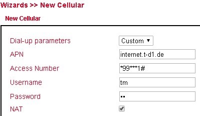
Parameter |
Description |
|---|---|
Dial-up parameters |
Auto or Custom |
APN |
The APN of the Internet provider is entered here |
Access Number |
Almost always 99**1# |
Username |
Username for the above APN, if necessary |
Password |
Password for the user name to the above APN, if it is necessary |
NAT |
Enable or disable NAT |
New IPsec Tunnel
Under Wizards > New IPsec Tunnel you can create a simple IPsec tunnel. It can be reconfigured later under VPN > IPsec.
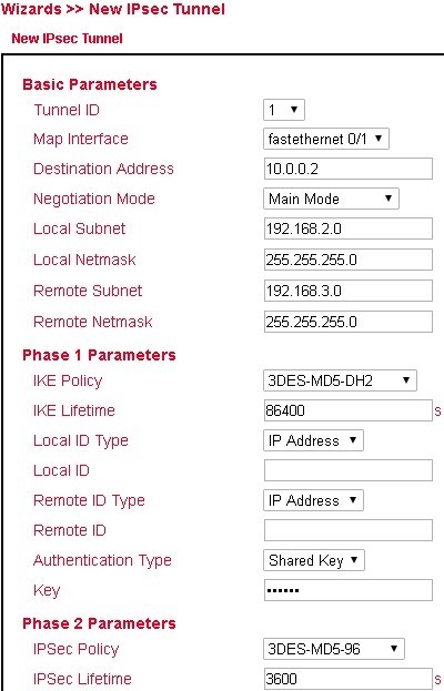
Basic Parameters:
Parameter |
Description |
|---|---|
Tunnel ID |
Serves for identification of the tunnel |
Map Interface |
Interface over which the IPsec tunnel is to be established. |
Destination Address |
Remote station of the IPsec tunnel |
Negotiation Mode |
Main Mode or Aggressive Mode (recommended Main Mode) |
Local Subnet |
The subnet of the router, which is to be reached by the remote station |
Local Netmask |
Subnet mask of the router |
Remote Subnet |
The subnet of the remote station |
Remote Netmask |
The subnet mask of the remote station |
Phase 1 Parameters:
Parameter |
Description |
|---|---|
IKE Policy |
Encryption / Hash / Diffie-Hellman-Group |
IKE Lifetime |
Period of validity of the IKE Policy |
Local ID Type |
IP address / FQDN / User FQDN |
Local ID |
IP address or FQDN |
Remote ID Type |
IP address / FQDN / User FQDN |
Remote ID |
IP address or FQDN |
Authentication Type |
Authentication method pre-shared key or certificate |
Key |
Pre-shared key |
Phase 2 Parameters:
Parameter |
Description |
|---|---|
IPSec Policy |
Encryption / Hash |
IPSec Lifetime |
Period of validity of the IPsec policy |
IPsec Expert Config
Under Wizards > IPsec Expert Config you can check the IPsec tunnel status by clicking Refresh. Furthermore, IPsec configurations can be imported via the interface.
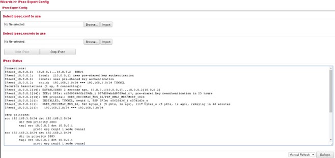
New L2TPv2 Tunnel
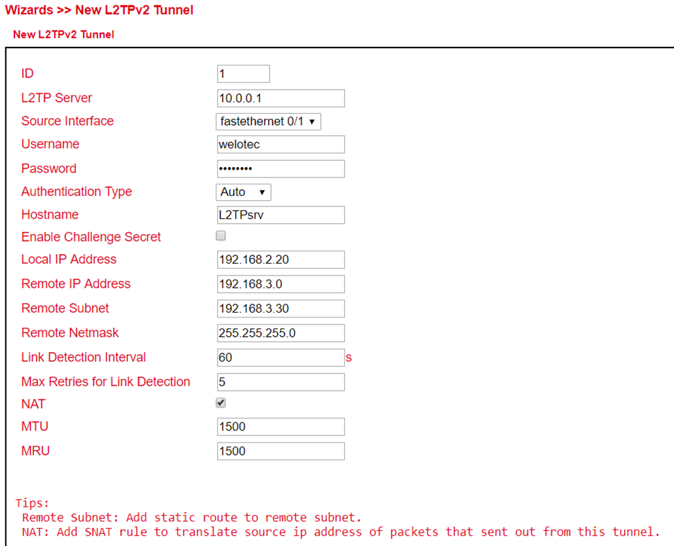
New Port Mapping
Under Wizards > New Port Mapping a new port mapping can easily be set up.
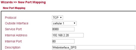
Parameter |
Description |
|---|---|
Protocol |
TCP or UDP |
Outside Interface |
The interface to be accessed from |
Service Port |
The port that is open to the outside |
Internal Address |
The internal IP address to be reached |
Internal Port |
The internal port to be reached |
Description |
Brief description |
If Cellular 1 is selected as Outside Interface, the port mapping only works if the cellular interface is assigned a public IP address! |
CLI Commands
In addition to the web interface, which can be accessed via the IP address of the router, it is also possible to configure and manage the router via the CLI (Command Line Interface). There are several ways to connect to the router via the CLI. For example, putty has proven itself as a tool for this.
One way to connect via the CLI is via SSH. However, this function must first be activated in the router. This is done via Administration > Management Services. Here the SSH function has to be enabled. The second way to connect to the router is via Telnet in connection with a serial console cable. To do this, Telnet must be enabled under Administration > Management Services, as with SSH, and the console cable must be connected to a computer at the router port labeled Console. Please save the changes with Apply&Save.
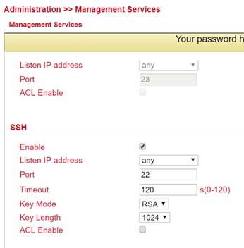
Then start e.g. putty and enter the IP address of your router and select SSH or TELNET as port or connection type. Then click on open to establish the connection to the router. If the connection is established successfully, you will get the CLI window with the login for the router.
Log in here with the credentials of your router (default user is adm and default password is 123456). If you have logged in successfully, you will see the following screen.
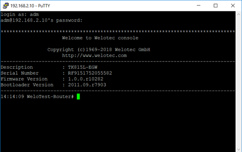
From here on you can use the following commands for help, analysis, configuration, etc.
Another way to connect to the router via the CLI is via a serial console cable. This is plugged into the console port of the router and connected to the PC.
Help Command
Help can be retrieved after entering help or “?” into the console, “?” can be entered at any time during command entry to get the current command or help from the command parameters, and the command or parameters can be auto-completed if only the command or command parameter is present.
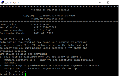
Entering help at the command prompt gives a short description of how to use the help command. If you append the “?” to a command, the possibilities that you can use in connection with the command are displayed. If there is no output, no or no further command exists for this input.
Show Command
The show command can be used to display parameters of the router or the configuration of the router. The help command or the “?” indicate the commands that can be used in combination with show.
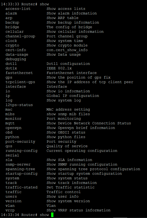
show version for example shows you data about the router, like the description, serial number, firmware and bootloader version.
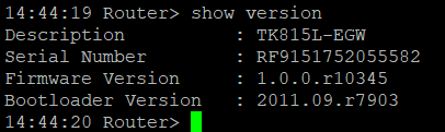
Ping Command
The ping command can be used to check whether the router has a connection to the Internet. The input form is, as usual with Windows, Ping Hostname or IP-Address.
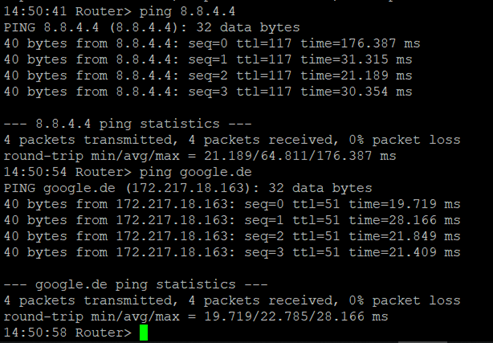
Traceroute Command
With traceroute you test the active routing of the specified destination. With traceroute hostname or IP address you start the query.
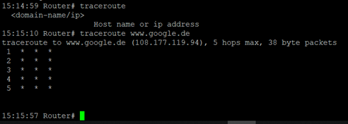
Reboot Command
To restart the router, you can use the reboot command. Enter it in the CLI and the router will be restarted.
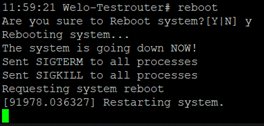
Configuration Command
In the superuser view, the router can use the configure command to switch the configuration view for management. A configure command can support no and default, where no indicates setting the abort of a parameter and default indicates restoring the default setting of a parameter. The configure terminal (or conf t for short) command switches the system to configuration mode. In this setting the router can be configured. To exit the configuration mode use the exit command. All entered commands must be terminated with the wr command so that the changes are applied to the router.
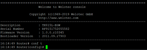
Hostname Command
In configuration mode, the router name can now be changed, for example. This is done with the command hostname name-of-router. This command changes the router name to the name you entered. If you want to reset the default name of the router, use the default hostname command. This resets the router name to the default router name.
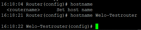
Clock set Command
With the clock set command you can configure the system date and time of the router via the CLI. The date and time format is as follows:
YYYY.MM.DD-HH:MM:SS
The complete command would then look like this
clock set 2019.01.24-12:00:00
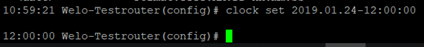

Enable password Command
It is always possible to change the password of the super user (adm) via the CLI. You can do this with the enable password command. The input format for this is
Enable password [password]
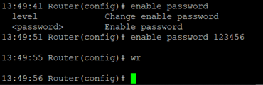
Username Command
The Username command allows you to create users to access the router. The syntax for the input is
Username [Username]
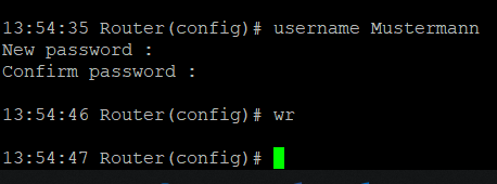
When creating the user, you will be asked for a new password that you can assign here. The user that is created is always a standard user.