Quick Start
Guide to installation and comissioning of the TK800 series. Please ensure that all package contents are present upon delivery. If you need a SIM card, contact your local network operator.
Package checklist
Each TK800 is supplied in a box with standard accessories. Optional accessories can also be ordered. Check the contents of the box. If something is missing, contact Welotec.
Components Router
Product |
Amount |
Description |
|---|---|---|
TK800 |
1 |
TK800 series industrial router |
Terminal block |
1 |
Terminal block, 2-pin |
Terminals Serial and I/O |
1 |
Terminal block, 9-pin (EX0 / EXW variants only) |
Components Set
Product |
Amount |
Description |
|---|---|---|
TK800 |
1 |
TK800 series industrial router |
Terminal block |
1 |
Terminal block, 2-pin |
Network cable |
1 |
1,5 m |
Antenna |
2 (4) |
3G/4G Antenna Wi-fi Antenna (EXW variant only) |
Power supply unit |
1 |
230 V AC to 12 V DC |
Terminals Serial and I/O |
1 |
Terminal block, 9-pin (EX0 / EXW variants only) |
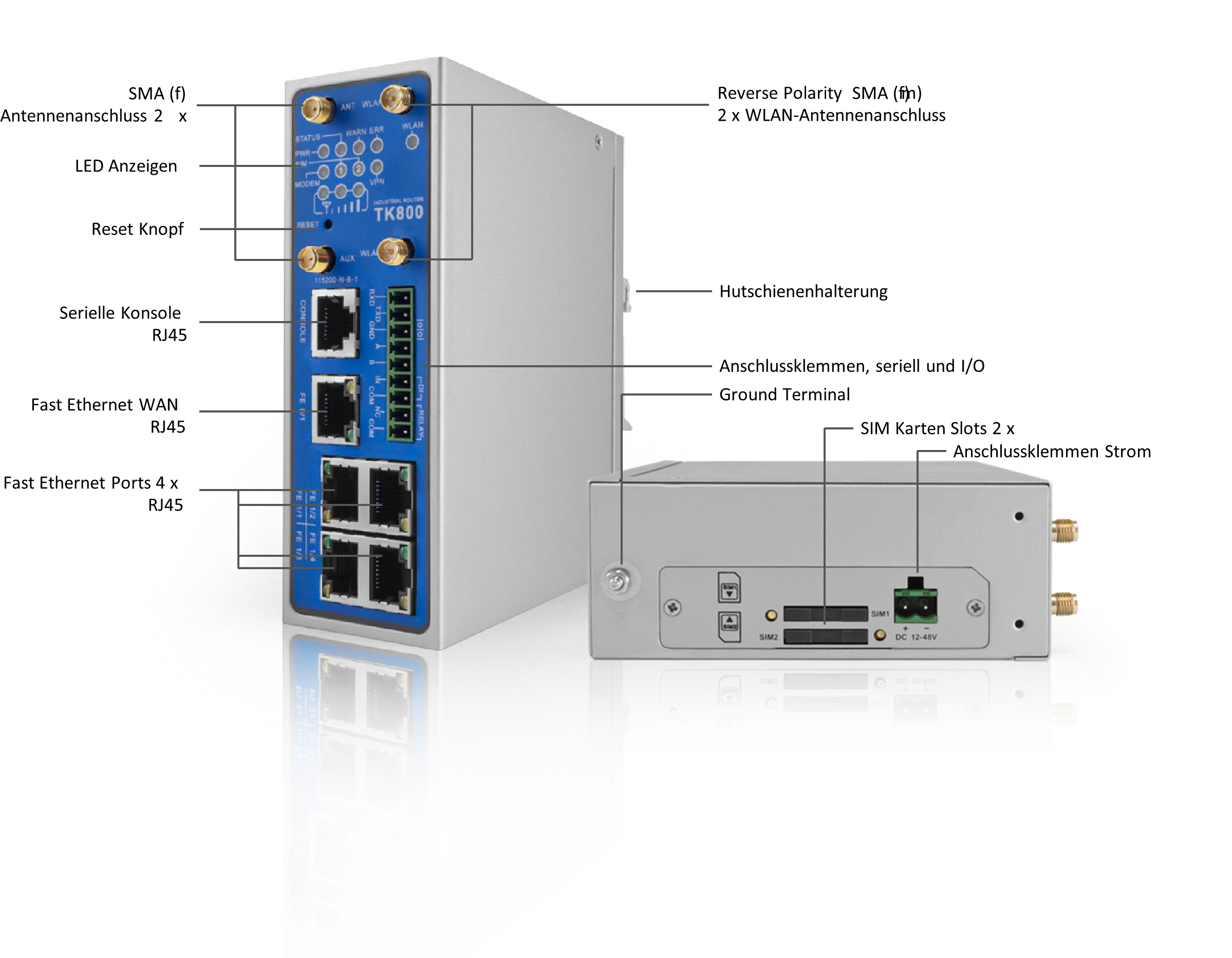
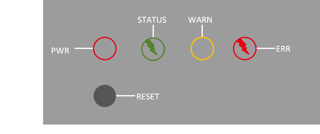
Information and Control Panel
Control Panel
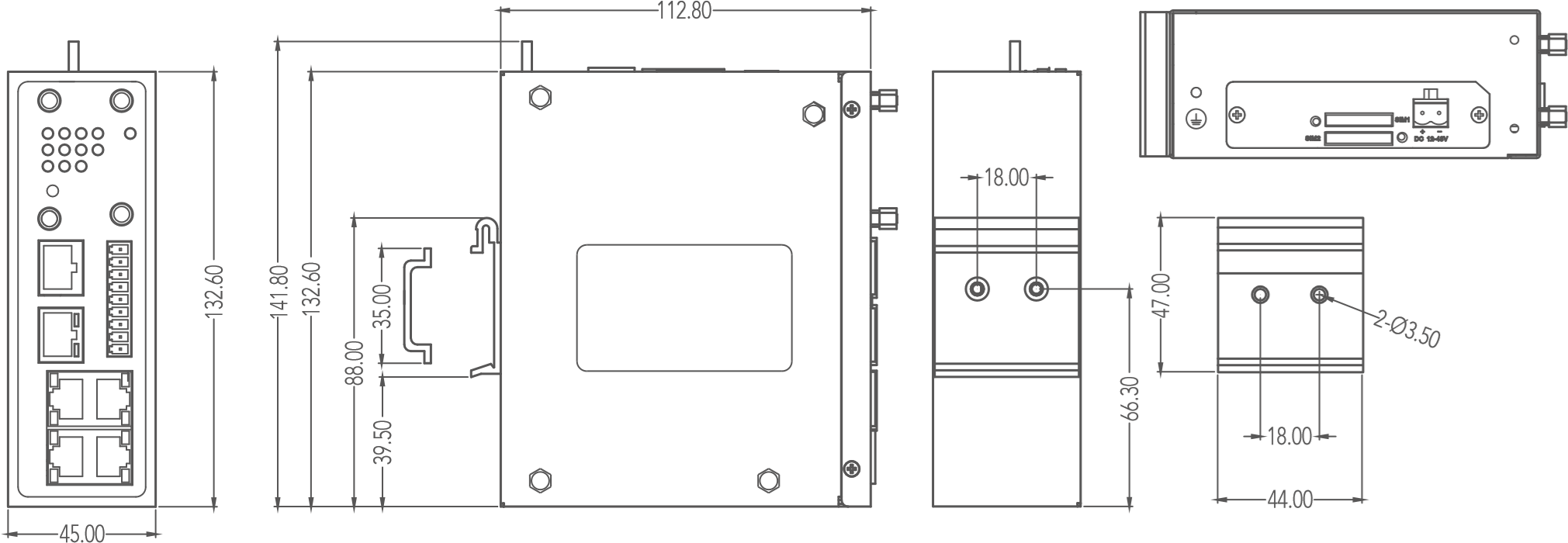
Dimension Drawings
Installation Guide
Preparations
Prepare the power supply (12 - 48 V DC). Make sure that the device can operate under the specified environmental conditions (working temperature range -25 – +70 °C, humidity: 5 – 95 % relative humidity). The device should not be exposed to direct sunlight and should be installed away from heat sources and environments with strong electromagnetic interference. The router can be mounted on a DIN rail (top-hat rail) or used at a workstation.
Mounting the Device
DIN rail:
Select a position with sufficient space on the DIN rail. Then place the upper part of the DIN rail mount on the DIN rail. Subsequently, press the lower side of the DIN rail mount down until the device is locked in place. This picture serves as an illustration:
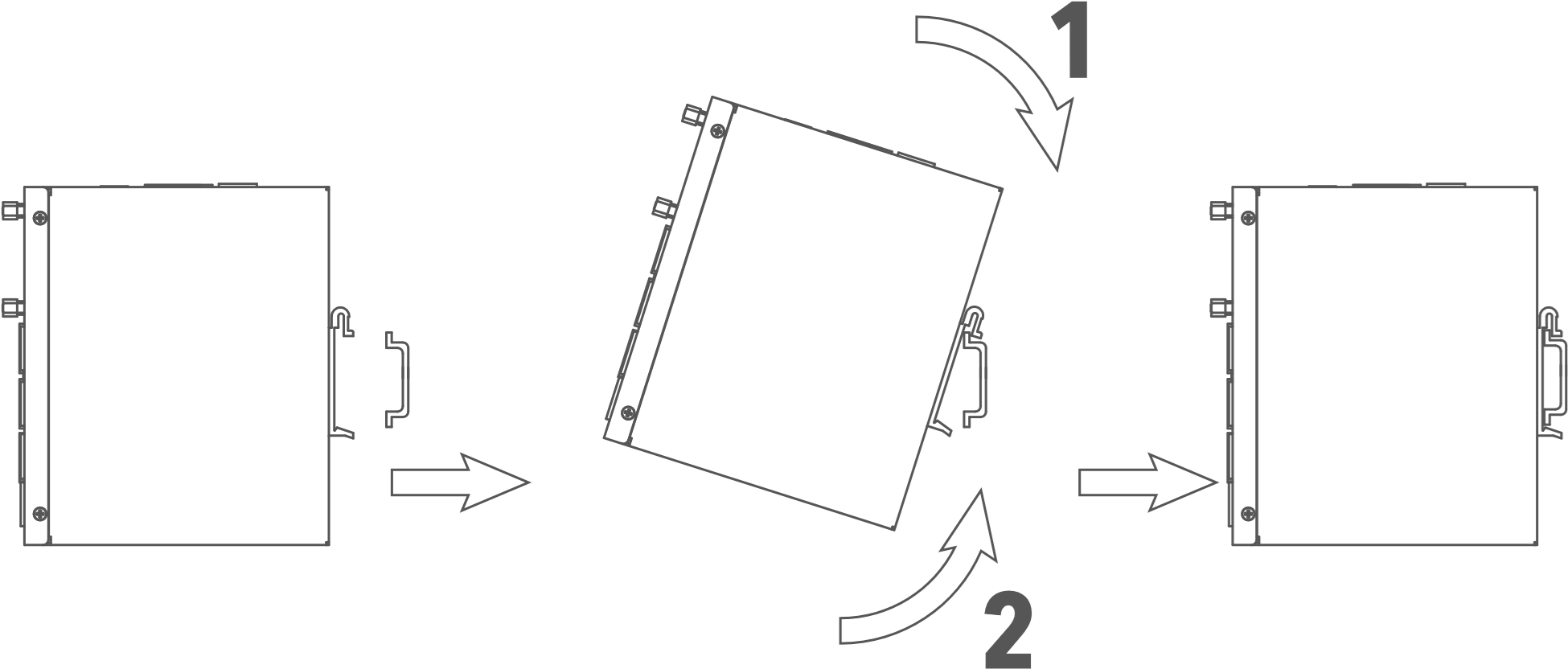
For demounting press the device from top to bottom and then pull the lower side of the device from the DIN rail (see figure).

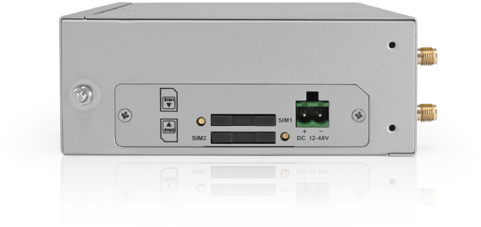
Installing the SIM Card
The TK800 supports dual SIM. To insert the cards, press the yellow “Eject” button with a small screwdriver on the top of the device, for example. The respective SIM card slot is pushed out. If the TK800 is not operated in dual SIM mode, use the SIM card slot “SIM1”.
Then insert the SIM card. The SIM card slot is not hot-pluggable. The router must be restarted after inserting the SIM card.
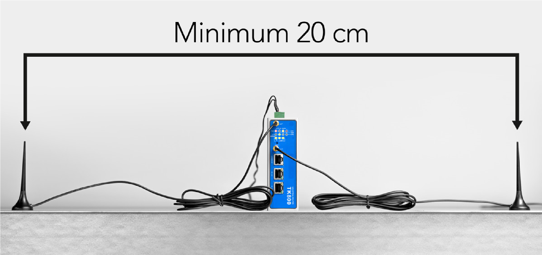
Antennas Installation
Plug the antennas onto the SMA connectors and turn the external attachment on the antenna cable until the connection is tight.

For optimal performance, place the antennas at least 20 cm apart.
Installation of the Power Supply
Remove the terminal block from the top of the router. Loosen the corresponding screws on the terminal block and route the wires to the corresponding terminals. The terminals are marked accordingly on the top of the router. Tighten the screws and then reinsert the connector block into the router.
To ground the device, use the grounding screw on the device.
To prevent interference due to electromagnetic influence, the housing of the router must be grounded via the grounding screw.
Cable Connections
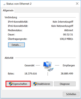
Connect the router to your PC via a network cable (RJ45). We recommend port FE 0/2 for all TK8x2 models and port FE 1/4 for all TK8x5 models.
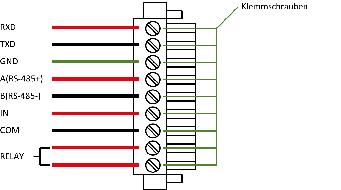
Connection of the Serial Interfaces and I/O’s
For the connection of the serial interfaces and the I/O’s you will find a terminal block on the front of the device. The individual contacts for this are labeled on the front of the device. Connect the lines according to these labels. The “IN” contact here represents the digital input, while the output is labeled “Relay”. “COM” represents the ground. This is a potential-free contact, i.e. what you put in at the IN contact comes out again at the relay contact, provided the contact is closed. Switching can be done via SMS and via the web interface. At 230 VAC the contact can be loaded with 2 Ampere. During installation, please remove the connection block from the device and connect the individual wires to the corresponding terminals. Then plug the connection block back onto the device.
This chapter describes only routers in the versions with serial interfaces and I/Os TK8XXX-EX.
Startup of the Router
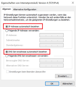
Automatic Configuration (DHCP)
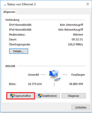
Configure the PC so that it works as a DHCP client (obtain IP address automatically). Connect the PC with a network cable to the interface FE0/2 or FE1/1 - FE1/4 (TK8X5 variants only). The PC is then assigned an IP address, standard gateway and DNS server by the router. The following figure shows the configuration process via DHCP on a PC with the Windows 10 operating system. The settings can be accessed via the Network and Sharing Center in Windows 10.
After configuring the IP address of the PC and connecting to the router, open a web browser.
Then enter “http://192.168.2.1” in the address line of your browser (e.g. Google Chrome). After confirming with the “Enter” key, a pop-up appears as the login page of the router. Enter the username (default: “adm”) and password (default: “123456”) here and confirm with “Enter”. Now you will be redirected to the configuration web page. Now configure the router according to your requirements.
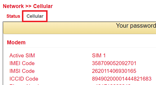
To check if you are connected to the Internet, select Network > Cellular > Status from the navigation panel. Here you can see the data of the cellular unit in the router. Alternatively, simply open a web page in your browser.
IP: |
192.168.2.1 |
|---|---|
Username: |
adm |
Password: |
123456 |
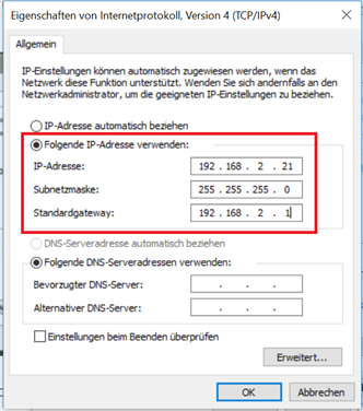
Manual Configuration
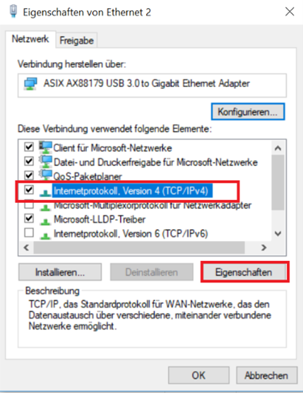
Configure your PC so that it is in the same subnet as the router (192.168.2.1). The subnet mask must be 255.255.255.0. The following image shows the process of configuring the IP address on a PC with the Windows 10 operating system.

After configuring the IP address of the PC and connecting to the router, open a web browser.
Then enter “http://192.168.2.1” in the address line of your browser. After confirming with the “Enter” key, a pop-up appears as the login page of the router. Enter the user name (default: “adm”) and the password (default: “123456”) and confirm with “Enter”. Now you will be redirected to the configuration web page. Now configure the router according to your requirements.
To check if you are connected to the Internet, select Network > Cellular > Status from the navigation panel. Here you can see the data of the cellular unit in the router. Alternatively, simply open a web page in your browser.
IP: |
192.168.2.1 |
|---|---|
Username: |
adm |
Password: |
123456 |
LED status lamps
Symbol explanation
 = LED leuchtet
  = LED leuchtet nicht
  = LED blinkt
There are two SIM card LEDs. When the router boots up, the SIM card LED for SIM card 1 is lit. In all other cases, the SIM card reception indicator is lit:
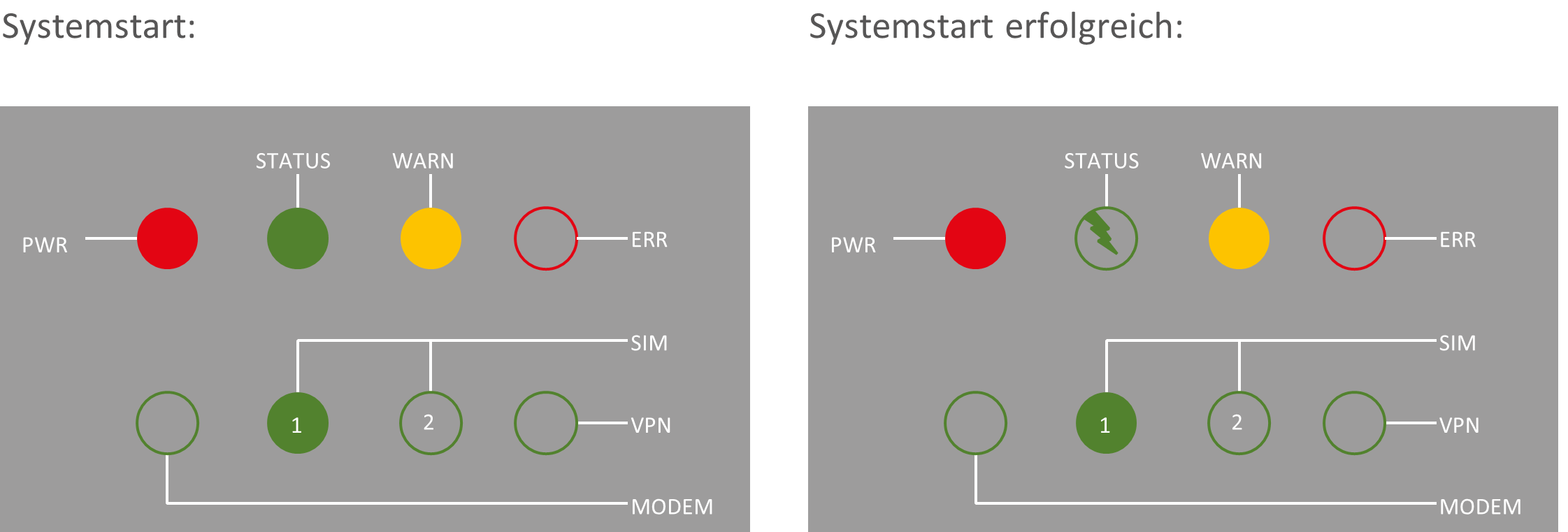
Dial-in: Dial-in successful:
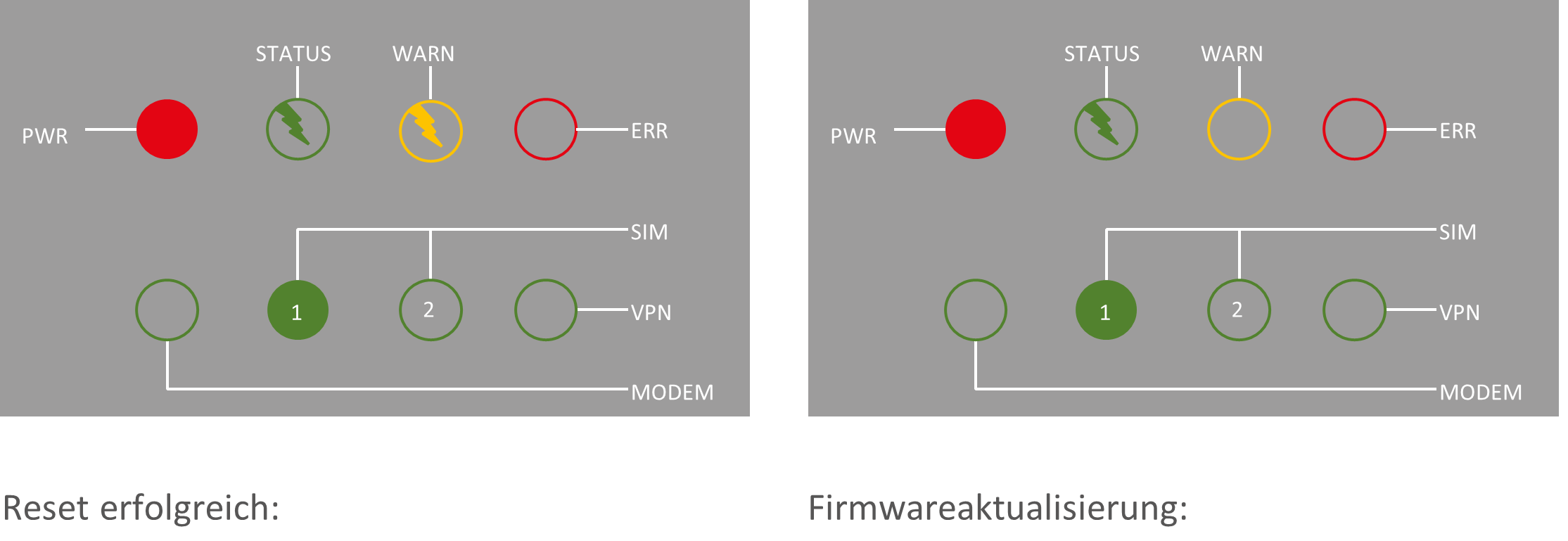
STATUS WARN STATUS WARN
SIM
VPN
PWR ERR PWR ERR
SIM
VPN
MODEM MODEM
Signal strength

Signal: 1-9
(poor signal, the router can not work correctly, please check the antenna connection and the local signal strength of the mobile network).
Signal: 10-19
(Router operates normally)
Signal: 20-31
(Perfect signal level)
Factory Reset
Hardware Method
Symbol explanation
= LED lights up = LED does not light up = LED flashes
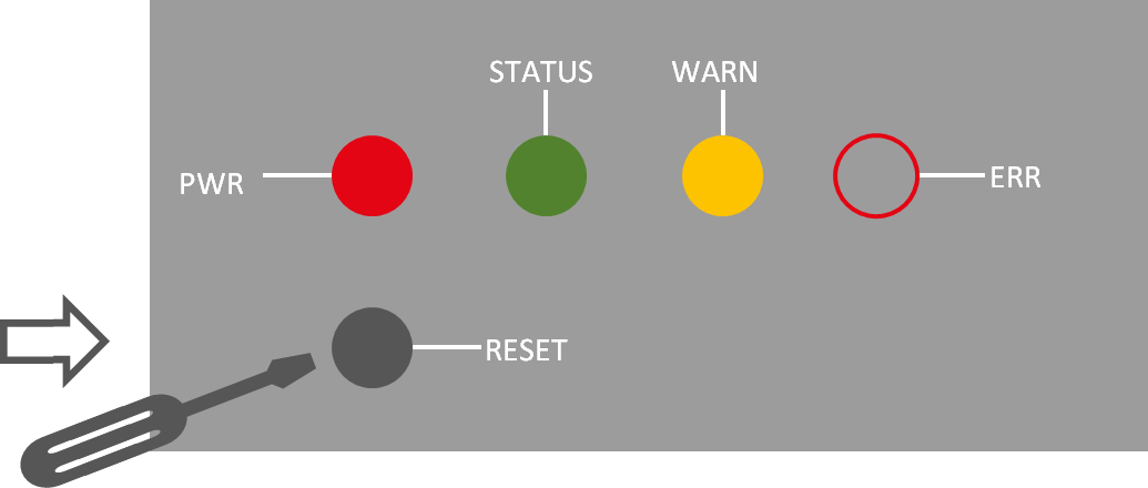
1) Press and hold the RESET button while turning on the TK800:
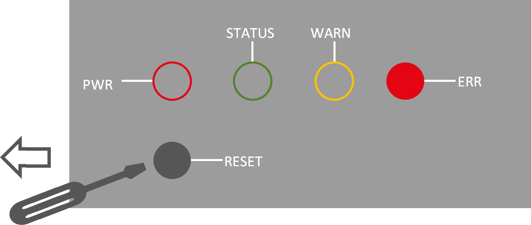
2) As soon as the ERROR LED lights up (approx. 10 seconds after switching on), release the RESET key:
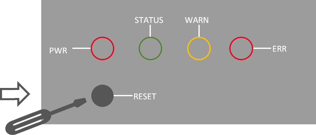
3) After a few seconds, the ERROR LED no longer lights up. Now press the RESET key again until the error light flashes and then release the key:
4) Now the ERROR and STATUS LED lights will flash, indicating that the factory reset was successful.
Factory default settings |
|
|---|---|
IP: |
192.168.2.1 |
Netmask: |
255.255.255.0 |
Username: |
adm |
Password: |
123456 |
Serial parameter: |
115200-N-8-1 |
Web Method
Go to the Config Management submenu via the Administration menu:
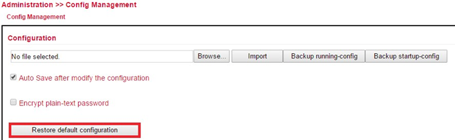
Click Restore Default Configuration to reset the TK800 to its default settings.
After a few seconds you will receive the following message. The router has now been successfully reset.After clicking reboot the router reboots to factory defaults.
Watchdog
Self Monitoring of the Router
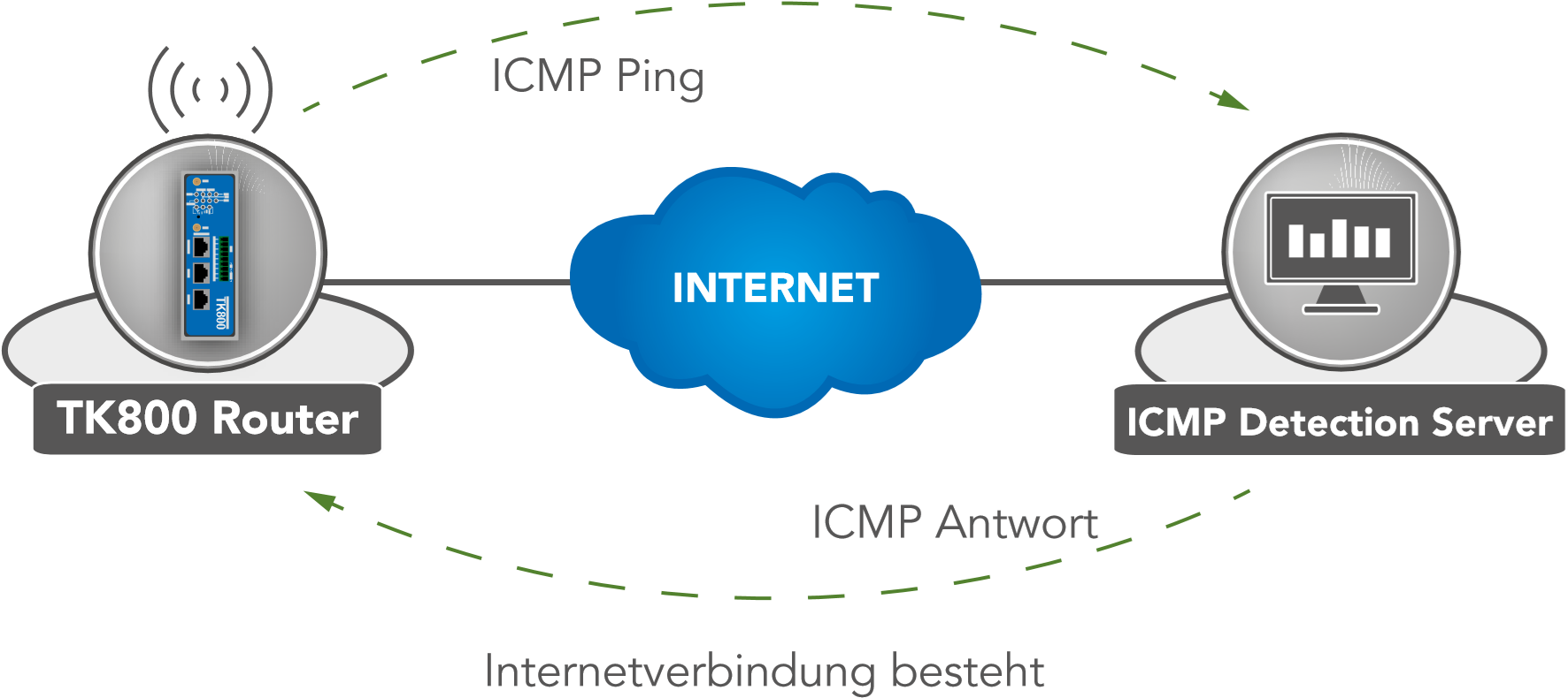
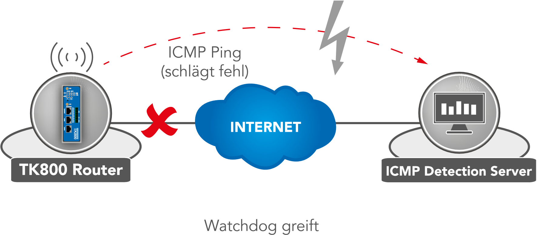
The watchdog monitors the router with regard to the Internet connection. The router itself checks whether there is an Internet connection as required. For this purpose, it sends ICMP packets to an individually defined server (ICMP detection server). If this query fails, the router first automatically restarts the dial-up, then the modem, and if necessary the entire system. The watchdog ensures a reliable Internet connection in the mobile network. This ensures that the router is almost always available.
Go via the menu item Network to the submenu item Cellular.
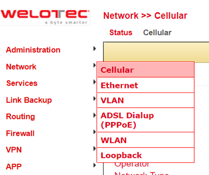
Select the Cellular tab
Now enter a suitable ICMP Detection Server in the corresponding field and change the ICMP Detection Interval.
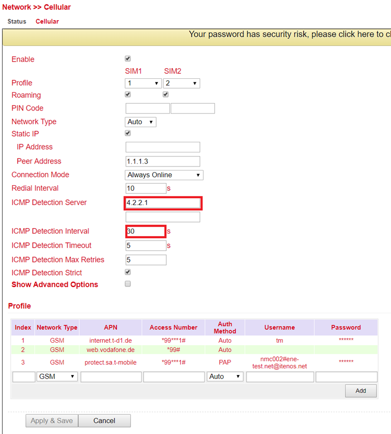
Note: The registered ICMP detection server should have a very high accessibility. A server from Google is no longer suitable for this, since the ICMP requests are blocked there.
Port Mapping / Port Forwarding
Access to Connected Devices via the Internet
To access devices connected to the Welotec router via the Internet, port mapping or port forwarding can be used. This is configured in the TK800 router via NAT rules.
Port mapping requires a public IP address in the mobile network (Public IP). If necessary, ask your mobile network provider or service provider about this!
The instructions refer to all TK800 routers with firmware 1.0.0.r10406 or higher.
The following image illustrates the application example (http uses TCP port 80 by default):
Private network (LAN) |
Public network (WAN) |
|
|---|---|---|
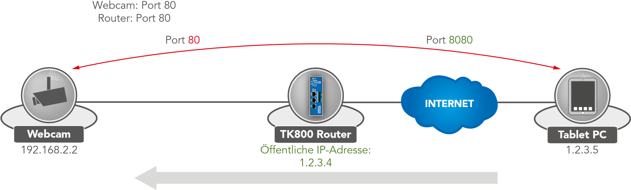
Package source: 1.2.3.4.8080 Destination: 192.168.2.2.80 |
Package source: 1.2.3.5.8080 Destination: 1.2.3.4.8080 |
|
|---|---|---|
Explanation:
Welotec Router |
|
|---|---|
LAN IP address: |
192.168.2.1 |
Subnet mask: |
255.255.255.0 |
IP camera |
|
|---|---|
LAN IP-Adresse: |
192.168.2.2 |
Subnet mask: |
255.255.255.0 |
Standard Gateway |
192.168.1.1 |
The IP camera has an interface that can be reached with a browser via http://192.168.2.2 (note: http protocol has TCP port 80).
Port Mapping Guide
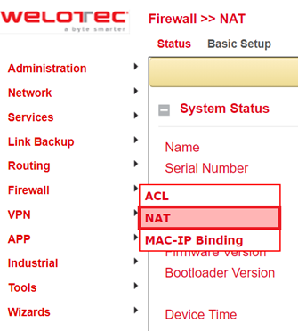
1) Go to the submenu item NAT via the menu item Firewall
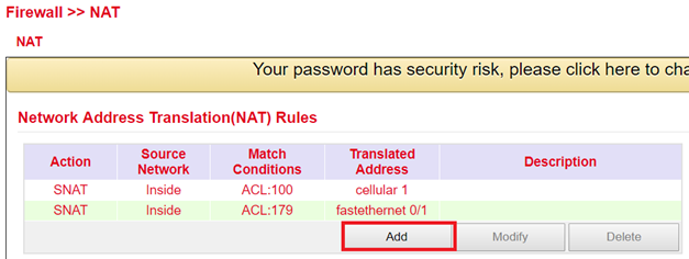
2) Now add a new NAT rule with Add
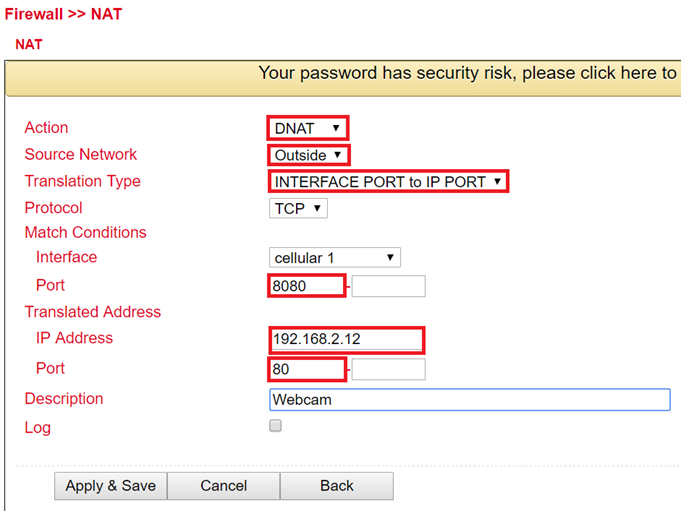
3) Enter the data as in the example
4) Afterwards the NAT rule appears in the Network Address Translation (NAT) Rules table as shown below
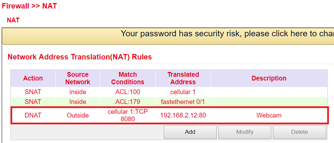
The rule is now active. The corresponding services restart and the port mapping is fully set up.
For a working port mapping it is helpful to check the settings of the connected devices in advance. The following checklist is helpful (according to the example above):
Does the camera have the IP address 192.168.2.12?
Does it respond at “ping 192.168.2.12”?
Is the web interface of the camera accessible via http://192.168.2.12?
Is the Welotec router entered as the default gateway for the camera (192.168.2.1)?
SMS Functions
The TK800 can be reached by SMS from the outside and reacts to various commands sent by SMS. One has the possibility to query the status of the device, to start / stop the dial-up or to restart the device.
Status Request / Restart
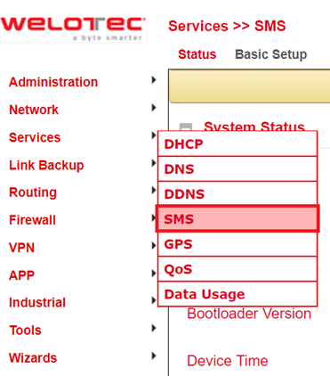
1) Go via the menu item Network to the submenu item SMS
2) Click the Enable checkbox to turn on the function
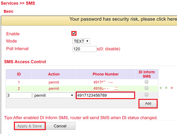
3) Enter in the table SMS Access Control the phone numbers (Phone Number) (format 4917123456789, no 0049 or +49!), which are allowed to send SMS to the router. Enter “permit” as action.
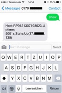
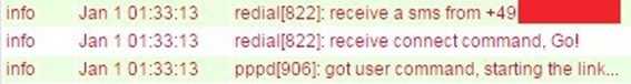
If now an SMS with the content show is sent to the mobile phone number of the router, the router sends its current status as response
If an SMS with the content reboot is sent to the router, it will reboot. You can also monitor this process in the log of the router

Connecting or Disconnecting from the Internet
After successful configuration, you can also control the router’s Internet connection via SMS. However, this requires the router to be set to “Connect On Demand”!
1) Go to the submenu item cellular via the menu item network.
2) Now select the cellular tab
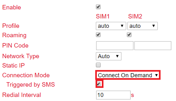
3) Under Connection Mode, select the Connect on Demand mode and activate the Triggered by SMS field.
Now you can send the following commands to the router via SMS:
cellular 1 ppp down - disconnects from the Internet

cellular 1 ppp up - establishes the Internet connection
Switch digital relay on or off
Another important SMS command is to switch the digital relay on or off via SMS.
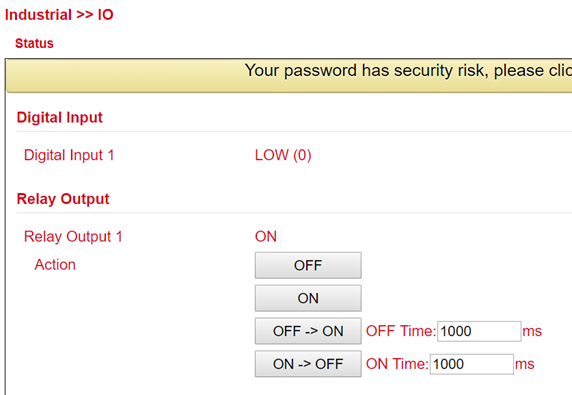
The following SMS commands can be used for this
io output 1 on - switches on the relay
io output 1 off switches off the relay